Sandvik Coromant hosts Global Press Preview Event

Published
April 07, 2017 - 03:45pm
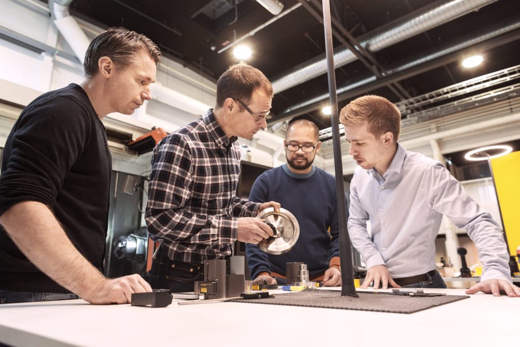
Creators of Sandvik Coromant's PrimeTurning technology

In the machine shop of the future, a digital thread will weave through the pre-, in- and post-machining processes. Prior to machining, those processes include design, process and operations planning, and production logistics. After machining, part verification and outbound logistics enter the picture.
This coming scenario was a central theme at the Global Press Preview Event held March 28-30 at the Sandvik Coromant Center in Sandviken, Sweden. In his presentation, Magnus Ekbäck, AB Sandvik Coromant’s vice president of business development and acting head of digital machining, said, as a result of this digital thread, the amount of tool software will increase three to four times by 2025. Meanwhile the amount of tool hardware will remain about the same.

One example of this software is Sandvik Coromant’s PrimeTurning code generator. PrimeTurning is compatible with various CNC systems and creates the ISO programming code and techniques for the toolmaker’s new turning methodology. According to the company, the PrimeTurning methodology enables parts manufacturers to perform longitudinal facing and profiling (forward and back), as well as conventional turning (from part end to chuck), with one tool.

More information by clicking here. However, I’d like to share the results of one application. After switching from conventional turning to the new methodology, an Italian manufacturer reduced the cycle time for a shaft from 2.42 to 1.36 minutes. It also extended the tool life per edge from four pieces to nine. The competitor’s conventional insert ran at a cutting speed of 150 m/min. (492 sfm), a feed rate of 0.3 mm/rev. (0.012 ipr) and a DOC of 2mm (0.079"). By contrast, the CoroTurn Prime B-type roughing insert (A-type is for finishing) ran at double the cutting speed and DOC and a feed of 0.8 mm/rev. (0.032 ipr) when turning forged, ASTM B564 nickel alloy with a hardness of 250 HB on a Doosan Puma 3100M horizontal machining center.

Related Glossary Terms

  • Brinell hardness number ( HB)

    Brinell hardness number ( HB)

    Number related to the applied load (usually, 500 kgf and 3,000 kgf) and to the surface area of the permanent impression made by a 10mm ball indenter. The Brinell hardness number is a calculated value of the applied load (kgf) divided by the surface area of the indentation (mm2). Therefore, the unit of measure of a Brinell hardness number is kgf/mm2, but it is always omitted.

  • computer numerical control ( CNC)

    computer numerical control ( CNC)

    Microprocessor-based controller dedicated to a machine tool that permits the creation or modification of parts. Programmed numerical control activates the machine’s servos and spindle drives and controls the various machining operations. See DNC, direct numerical control; NC, numerical control.

  • cutting speed

    cutting speed

    Tangential velocity on the surface of the tool or workpiece at the cutting interface. The formula for cutting speed (sfm) is tool diameter 5 0.26 5 spindle speed (rpm). The formula for feed per tooth (fpt) is table feed (ipm)/number of flutes/spindle speed (rpm). The formula for spindle speed (rpm) is cutting speed (sfm) 5 3.82/tool diameter. The formula for table feed (ipm) is feed per tooth (ftp) 5 number of tool flutes 5 spindle speed (rpm).

  • feed

    feed

    Rate of change of position of the tool as a whole, relative to the workpiece while cutting.

  • hardness

    hardness

    Hardness is a measure of the resistance of a material to surface indentation or abrasion. There is no absolute scale for hardness. In order to express hardness quantitatively, each type of test has its own scale, which defines hardness. Indentation hardness obtained through static methods is measured by Brinell, Rockwell, Vickers and Knoop tests. Hardness without indentation is measured by a dynamic method, known as the Scleroscope test.

  • machining center

    machining center

    CNC machine tool capable of drilling, reaming, tapping, milling and boring. Normally comes with an automatic toolchanger. See automatic toolchanger.

  • profiling

    profiling

    Machining vertical edges of workpieces having irregular contours; normally performed with an endmill in a vertical spindle on a milling machine or with a profiler, following a pattern. See mill, milling machine.

  • turning

    turning

    Workpiece is held in a chuck, mounted on a face plate or secured between centers and rotated while a cutting tool, normally a single-point tool, is fed into it along its periphery or across its end or face. Takes the form of straight turning (cutting along the periphery of the workpiece); taper turning (creating a taper); step turning (turning different-size diameters on the same work); chamfering (beveling an edge or shoulder); facing (cutting on an end); turning threads (usually external but can be internal); roughing (high-volume metal removal); and finishing (final light cuts). Performed on lathes, turning centers, chucking machines, automatic screw machines and similar machines.

Author

Editor-at-large

Alan holds a bachelor’s degree in journalism from Southern Illinois University Carbondale. Including his 20 years at CTE, Alan has more than 30 years of trade journalism experience.

Sponsored Content