Simplified CAM for advanced EDM wire cutting
Simplified CAM for advanced EDM wire cutting
The cutting of intricate profiles and odd angles is the domain of wire EDM machining processes, capable of creating ultraprecise shapes and superior finishes that are near-impossible to machine by other means. However, just because a shape is difficult to machine does not mean it should be hard to program.

The cutting of intricate profiles and odd angles is the domain of wire EDM machining processes, capable of creating ultraprecise shapes and superior finishes that are near-impossible to machine by other means. However, just because a shape is difficult to machine does not mean it should be hard to program.
Working with wire and water, instead of speeds and feeds, presents a challenge for CAM systems originally developed for conventional milling and turning applications. The concept of removing material with a cutter does not translate easily to the concept of eroding material with a thin wire. Yes, nomenclature such as "contouring" and "pocketing" ultimately means the same thing in the end product, but the means to the end are vastly different with wire EDM.
Working with wire and water requires an EDM-first perspective in CAM development to open a world of opportunities for innovation in metalworking. ESPRIT has become a leader in wire EDM by consistently supporting innovation in programming. Innovation begins by challenging traditional thinking. But innovation also benefits by applying traditional methods in untraditional ways.
Recognizing that EDM Part Shapes are Unique
Slicing through metal with an energized wire is a very efficient way to cut intricate shapes. Those intricate part shapes have physical properties unique to the wire-cutting process. Constant tapers, variable tapers, vertical land areas, sharp corners, radius corners, sharp corners that taper into radius corners, and the list goes on. A first step to simplifying the programming process is for a CAM system to recognize and retain knowledge of those unique properties so that wire programming can be automated.
ESPRIT is a feature-based CAM system that automatically recognizes the machinable features that are specific to wire machining. Choices include die (pocket), punch (boss), hole, open profile, and even turning profile features for wire machines equipped with a rotary table. An emphasis is placed on fast and easy creation of machinable features for wire EDM. Detailed properties about XY and UV profiles, workpiece height, tapers and corner styles are associated with the EDM features so that, regardless of the type or number of operations applied to the feature, the integrity of the underlying data remains the same. When EDM properties are embedded in the feature, the entire programming process is streamlined because most of the data needed for programming is coming from a single, reliable source.
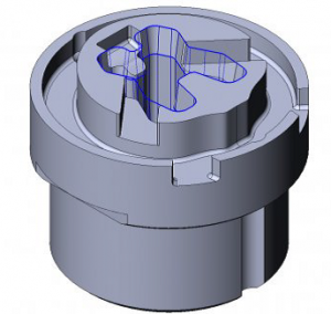
ESPRIT Feature Recognition only recognizes walls that can be cut with wire EDM and ignores the rest. All images courtesy of DP Technology
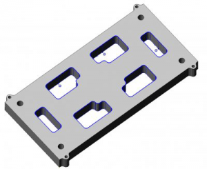
ESPRIT automatically recognizes all die openings in a plate with a single click.
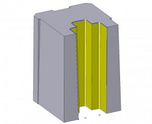
When only certain walls need machining, individual solid faces are easily selected for feature recognition.
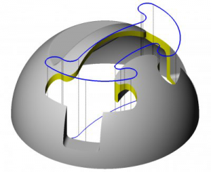
ESPRIT detects maximum and minimum plane heights and accurate profiles, even on curved walls.
Building Flexibility into a Wire Solution
ESPRIT Wire EDM has a long tradition with wire EDM partners, customers, and experts of consistently understanding the needs of the field and providing innovative solutions. Synchronized computer control of the machine's upper and lower wire guides allows the machining of extreme tapers, compound tapers, and the blending of independent top and bottom profiles on one workpiece. ESPRIT reportedly ensures that the wire follows a complex path in a steady, highly controlled manner.
When an EDM operation is created in ESPRIT, all rough, skim and tab cuts are created as separate entities. This method offers two advantages. First, the programmer can easily change the order of cuts, either manually for a few cuts, or automatically using an advanced sorting function to change the order of all cuts in a single command. This is a distinct advantage when cutting a series of multiple profiles. Secondly, although the cuts are generated separately, they remain under the control of the original operation defined by the programmer. If a minor change is required, the programmer only needs to change that single operation to automatically regenerate all the associated cuts. Using a parent/child relationship in an EDM program offers maximum flexibility and ease-of-use.
Using Divide and Conquer to Tackle Odd Shapes
EDM programmers rely on two basic methods of material removal inside a pocket cavity. The first is a contouring operation that follows the profile of the opening, followed by a slug drop to remove the material in one piece. The second method, called no-core pocketing, is used when a slug is too small or too intricate to remove easily. In this method, the wire gradually erodes all the material inside a cavity with progressively offset cutting passes.
One advantage of ESPRIT for wire EDM is the ability to easily combine strategies for the most efficient material removal. ESPRIT makes it easy to combine strategies and customize the order of cuts to maximize efficiency.
Let's take the case of a die profile that is relatively uncomplicated, except for small openings along the edges. If the wire for the rough cut is too big to fit into the small openings, the profile can be contoured first in G40 mode with look-ahead to prevent the wire from entering the small openings. Once the slug is dropped, a no-core pocketing operation can follow to burn away only the small amount of material that remains. Then the same contouring operation will skim the entire profile because look-ahead will now recognize that the openings have been cleared of material.
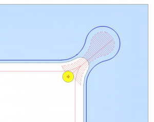
Combine contouring on large profiles with no-core pocketing on small openings to efficiently cut awkward 2-axis profiles.
ESPRIT's 4-axis pocketing takes this concept a step further. Built-in options will automatically identify and isolate the largest area inside a complex cavity that can accommodate a slug drop. This "core" area is removed with a simple 2-axis contouring operation. Then, 4-axis no-core pocketing wire path is applied to remove only the material that remains.
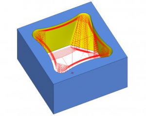
Four-axis pocketing detects the largest area for a slug drop, then applies no-core pocketing only to the remaining material for faster machining of complex cavities.
Compensating for Previous Material Removal
Sometimes, a big hole or a groove is premachined inside a pocket cavity to remove as much material as possible and, at the same time, release the stress within the material. Other times, a model has a cast pocket cavity and the inside profile could be of any reasonable shape. Pocketing passes must recognize and adapt to the shape of an internal cavity to avoid cutting air.
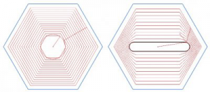
ESPRIT's no-core pocketing offers the option of a constant offset around a predrilled hole or a smooth transition between the shape of an internal cavity and an outer profile.
Trusted Unattended Machining
Wire machines offer features that enable them to operate for extended periods of time without the close attention of an operator. These features include automatic wire threaders, tooling fixtures for multiple part setups, sensing and feedback systems for adaptive control, and advanced electronics. There is great potential for around-the-clock production by grouping workpieces and processing them consecutively, such as similar stamping die details that can be set up in multiples. However, accommodating this kind of work requires advanced programming ability to achieve the greatest reliability and cost savings.
ESPRIT includes machining strategies that automatically add stops at a specified distance along the wire path for slug retention, generates the appropriate skim cuts, and then automatically retraces the path to remove the stops in the proper sequence for safely releasing the slug. For flexibility, the program can be instructed to wait until an operator is present before cutting the stops.
It is also important to have an accurate estimate of cut time for each part program. Reliable estimates are vital to scheduling and planning unattended operation for the available hours. When setting up a job to run overnight, an accurate time estimate will ensure the job will be done in the morning. Programmers can view cycle times in an ESPRIT document or quickly generate a complete and accurate report of all operation cycle times and total cycle time, plus all thread locations, wire and workpiece data, and any specific setup instructions. Automating the wire EDM process can help a shop succeed by reducing production costs and improving responsiveness.
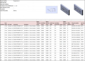
A detailed report gives an accurate estimate of cut time for unattended machining.
User-Guided Automation and Customization
ESPRIT provides a universal data reader that gives users access to manufacturer-recommended cut data for their make and model of EDM. The ESPRIT EDM Expert System is an integrated component of ESPRIT Wire EDM, accessed from any EDM operation page. The programmer chooses the wire size and workpiece data to display optimal cutting strategies. Once a strategy is chosen, the manufacturer-recommended values are loaded into the operation with a single click.
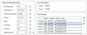
The ESPRIT EDM Expert System makes it easy to access and customize manufacturer-recommended EDM cut data.
Using the databases provided by ESPRIT as a baseline, wire EDM users have the option to modify the data while they work to more finely tune the way they cut parts and create customized cut strategies. Changes to the database can be saved to a new file or the current database can be overwritten. The EDM cut data is stored in external XML files that are simple to use and easy to update. However, instead of exiting ESPRIT and working with XML code directly, the Expert System lets programmers edit their database directly within the ESPRIT work environment. This simplified method of editing data in a familiar environment lets EDM programmers test and fine-tune cut strategies quickly while they work, without the need to learn XML coding.


