BobCAM for SolidWorks

Contact Details

BobCAD-CAM Inc.
Address
1729 Bucknall Rd.
Campbell
95008-2502
CA
United States
Phone
408-436-7777
Toll Free Phone
800-732-3051
Fax
408-436-7910
April 01, 2010

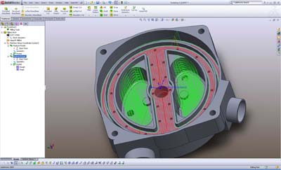
BobCAD-CAM software has released their BobCAM for SolidWorks add-in for SolidWorks design software customers worldwide. SolidWorks customers can now take advantage of the BobCAM automatic 2, 3 and 4th axis machining capabilities without having to use a separate CAM system for toolpath and G-Code programming for CNC machining. The primary benefit of BobCAM is that machining operations can be defined, calculated and verified without leaving the parametric SolidWorks design environment. All 2-, 3- and 4-axis machining features are fully associative to the part model. If you make any changes to your SolidWorks model, all your CAM operations are easily updated. Full associativity between the SolidWorks design and machining operations in the new CAM tree effectively reduces errors when the part model is changed. The user has the ability to create special tool patterns for hole drilling as well as any of the other machining strategies offered in BobCAM. These tool patterns and cutting conditions can be associated with the specific part being machined or used globally throughout the system. The user simply loads the machining feature, selects the model and BobCAM loads all of the depths and correct tools for the operation. Then the user can further customize the operations and automatically generate the toolpaths and G-code program for the machine of choice. BobCAM offers functionality for profiling, pocketing, engraving, plunge roughing as well as the more advanced 3-axis toolpaths, such as Z-Level roughing and finishing operations. BobCAM provides a material and tool database that can be customized as well as fully customizable post processors for CNC milling, routers, waterJet, laser and burning machines. BobCAM includes virtual toolpath simulation, RS 232 communications and DNC capabilities. BobCAM comes with a comprehensive built-in help system as well as user training manual.
Related Glossary Terms

  • G-code programming

    G-code programming

    Programs written to operate NC machines with control systems that comply with the ANSI/EIA RS-274-D-1980 Standard. A program consists of a series of data blocks, each of which is treated as a unit by the controller and contains enough information for a complete command to be carried out by the machine.

  • burning

    burning

    Rotary tool that removes hard or soft materials similar to a rotary file. A bur’s teeth, or flutes, have a negative rake.

  • computer numerical control ( CNC)

    computer numerical control ( CNC)

    Microprocessor-based controller dedicated to a machine tool that permits the creation or modification of parts. Programmed numerical control activates the machine’s servos and spindle drives and controls the various machining operations. See DNC, direct numerical control; NC, numerical control.

  • computer-aided manufacturing ( CAM)

    computer-aided manufacturing ( CAM)

    Use of computers to control machining and manufacturing processes.

  • direct numerical control ( DNC)

    direct numerical control ( DNC)

    Method of transferring CNC code from the CAD/CAM system to the machine tool.

  • gang cutting ( milling)

    gang cutting ( milling)

    Machining with several cutters mounted on a single arbor, generally for simultaneous cutting.

  • milling

    milling

    Machining operation in which metal or other material is removed by applying power to a rotating cutter. In vertical milling, the cutting tool is mounted vertically on the spindle. In horizontal milling, the cutting tool is mounted horizontally, either directly on the spindle or on an arbor. Horizontal milling is further broken down into conventional milling, where the cutter rotates opposite the direction of feed, or “up” into the workpiece; and climb milling, where the cutter rotates in the direction of feed, or “down” into the workpiece. Milling operations include plane or surface milling, endmilling, facemilling, angle milling, form milling and profiling.

  • profiling

    profiling

    Machining vertical edges of workpieces having irregular contours; normally performed with an endmill in a vertical spindle on a milling machine or with a profiler, following a pattern. See mill, milling machine.

  • toolpath( cutter path)

    toolpath( cutter path)

    2-D or 3-D path generated by program code or a CAM system and followed by tool when machining a part.

Sponsored Content