EDGECAM CAD/CAM Software Upgrade
EDGECAM CAD/CAM Software Upgrade
A number of these productivity boosts have been achieved by reducing calculation time with EDGECAM 2021's enhanced parallel-processing capability. Two of the most popular machining cycles – Roughing and Profiling – benefit from improvements to the software's multi-threading technology algorithms. Three significant time savings: EDGECAM's world-leading high-speed Waveform Roughing strategy is now significantly faster when generating toolpath for both solid and wireframe components.

New and enhanced functionality in the latest release of EDGECAM CAD/CAM software from Hexagon Production Software boosts customer productivity with lower computer-processing time and faster toolpaths.
A number of these productivity boosts have been achieved by reducing calculation time with EDGECAM 2021's enhanced parallel-processing capability. Two of the most popular machining cycles – Roughing and Profiling – benefit from improvements to the software's multi-threading technology algorithms.
Three significant time savings: EDGECAM's world-leading high-speed Waveform Roughing strategy is now significantly faster when generating toolpath for both solid and wireframe components.
Machining Market and Product Manager Miguel Joha says, "Numerous benchmark tests show a 30 percent improvement in calculation times compared to the previous version." When using the profiling cycle's Undercut function, savings of between 40 and 60 percent have been recorded, depending on the part's size and complexity. Additionally, improvements to the software's architecture give an average time saving of 70 percent on checking toolpaths with Machine Simulator when the software is initially launched.
A radical overhaul of probing functionality revolves around eight new cycles, which deliver support for programming a variety of on-machine probing cycles. The cycles' NC output can be configured to support Hexagon's existing m&h probing macros, as well as many other popular probing systems for different controls and native probing languages of Siemens and Heidenhain controls.
Following specific customer requests, six new or updated commands have been introduced into the inspection operation, including the ability to globally edit existing features, and to specifically control the layout of both linear and rectangular-array features.
One of EDGECAM's most used strategies, the Face Mill Cycle now offers better toolpath control, reductions to cycle times, less tool wear, and can potentially increase machine tool longevity.
In addition to time savings, the new Cut by Region option deploys a more even toolpath, completing each segment of a component before moving on to another region. Another newcomer – Outside To In strategy – promotes more intelligent toolpaths, as well as reducing cycle times. Previously, when set to either Climb or Conventional, the face mill cycle took longer as it moved from left to right in readiness for the feed movement. Now, however, closer cutter contact reduces that time. Also, a new Overlap Edge function guarantees no wasted cutter passes, and no surplus material left on a face.
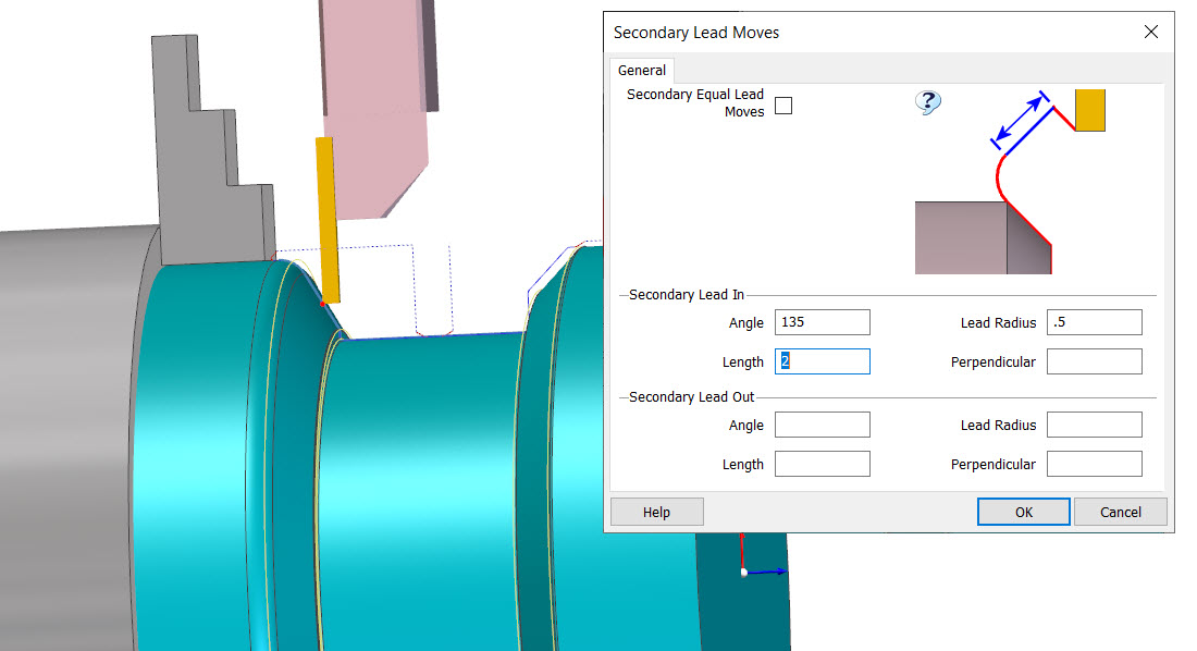
Extra Lead In/Out functionality for lathes gives more control during the secondary movement of the Finish Groove cycle. Applications Engineer Mike O'Neill explains, "Groove features come in all shapes and sizes, and aren't always symmetrical. EDGECAM 2021 includes a Secondary Lead Move dialog, meaning that as the cycle completes the opposite side of a groove feature, the user can now deploy unique Lead In and Lead Out movements."
A further turning-related enhancement incudes more control when working with angled turning tools. Two new modifiers, 'Corner' and 'Lock,' will enable a 'dynamic gauge point,' which maintains the same position in relation to the insert at all orientations.
Dovetail tool cutters, which were introduced in the previous version of EDGECAM, can now be used with a Profiling cycle in both milling and turning environments. Solid Features and Faces can be selected in conjunction with the Undercut command for back-facing and other collision-free toolpaths. "Also, in response to customer requests, the Protect Solid function found in the Profiling cycle has been enhanced to give safer toolpaths when using the Multi-Pass and Pick Solid Face commands."
The 2021 release includes two important new machine tool configuration features to harness best practice. "Variable pitch and multiple axis support on tool mounting blocks has been introduced in Linear Turret Lathes kinematics. Using a simple switch in the Code Wizard to stipulate the exact position of numerous tool stations on a turret, while clearly showing this in the Machine Simulator.
"'Multi-Task Machine Tools' can now support cutting tools mounted inside Angle Head attachments. This type of tool configuration has been used in EDGECAM's milling environment for a number of years, so MTMT users are benefiting from a mature feature that's been thoroughly tried and tested."
Finally, Wire EDM includes a new strategy to the Wire Set-Up command and extended controller support. The 'create pocket rough tag and finish files' strategy supports industry best practice and allows users to create four separate NC files for Pocketing, Roughing, Tag creation, and Finishing. Technology tables for Charmilles and ONA AV have been added, along with enhanced support for a range of Mitsubishi controllers.


