FANUC CNC Simulator

March 15, 2016

FANUC America Corp. has released the new FANUC CNC simulator, bringing the popular CNC to the classroom and providing students with exposure to FANUC CNCs without the need for a full mill or lathe. The FANUC CNC simulator is based on the FANUC series 0i - Model F platform and can be operated in either milling or turning configurations. Students can program the simulator as a 3-axis mill or a 2-axis/1-spindle turning system. The simulators are portable and require only a standard wall outlet for power.
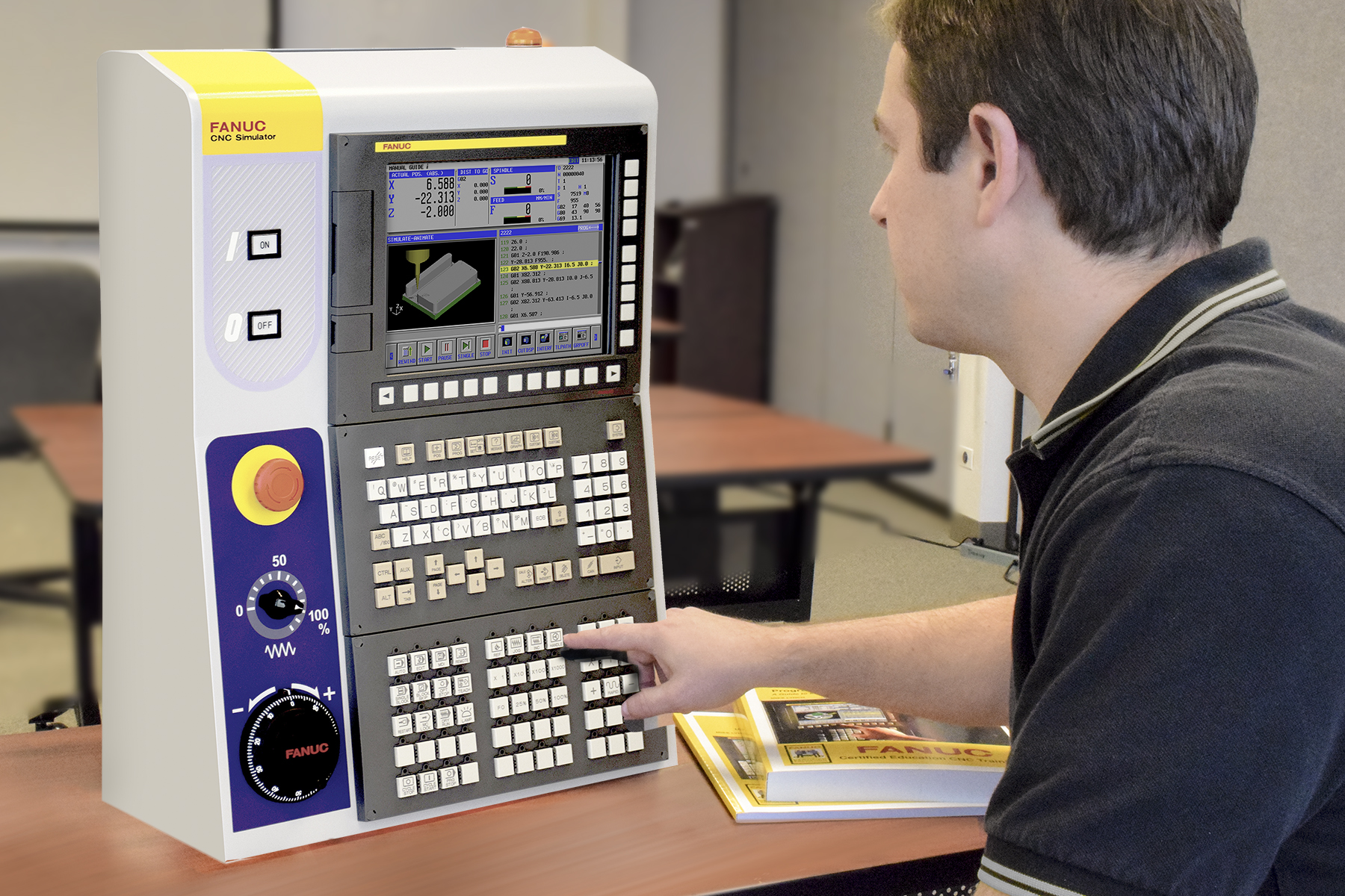
The CNC simulator is a complete FANUC CNC with a 10.4” LCD monitor and a QWERTY keyboard, so students will experience the look, feel and layout of the control as they navigate and program a fully functioning CNC. Students can transfer the programs to the machines using the built-in Ethernet connections or standard Flash ATA or USB interface.    

The FANUC CNC simulator comes loaded with FANUC Manual Guide i conversational programming interface, which allows users to graphically generate programs that are simulated in 3-D prior to being converted back to conventional NC programs and used on machine tools. The interface simplifies programming and enhances productivity. By learning process-oriented conversational programming students can focus on machine operations instead of just G code, which leads to faster, more efficient operations.

Related Glossary Terms

  • 3-D

    3-D

    Way of displaying real-world objects in a natural way by showing depth, height and width. This system uses the X, Y and Z axes.

  • computer numerical control ( CNC)

    computer numerical control ( CNC)

    Microprocessor-based controller dedicated to a machine tool that permits the creation or modification of parts. Programmed numerical control activates the machine’s servos and spindle drives and controls the various machining operations. See DNC, direct numerical control; NC, numerical control.

  • conversational programming

    conversational programming

    Method for using plain English to produce G-code file without knowing G-code in order to program CNC machines.

  • flash

    flash

    Thin web or film of metal on a casting that occurs at die partings and around air vents and movable cores. This excess metal is due to necessary working and operating clearances in a die. Flash also is the excess material squeezed out of the cavity as a compression mold closes or as pressure is applied to the cavity.

  • gang cutting ( milling)

    gang cutting ( milling)

    Machining with several cutters mounted on a single arbor, generally for simultaneous cutting.

  • lathe

    lathe

    Turning machine capable of sawing, milling, grinding, gear-cutting, drilling, reaming, boring, threading, facing, chamfering, grooving, knurling, spinning, parting, necking, taper-cutting, and cam- and eccentric-cutting, as well as step- and straight-turning. Comes in a variety of forms, ranging from manual to semiautomatic to fully automatic, with major types being engine lathes, turning and contouring lathes, turret lathes and numerical-control lathes. The engine lathe consists of a headstock and spindle, tailstock, bed, carriage (complete with apron) and cross slides. Features include gear- (speed) and feed-selector levers, toolpost, compound rest, lead screw and reversing lead screw, threading dial and rapid-traverse lever. Special lathe types include through-the-spindle, camshaft and crankshaft, brake drum and rotor, spinning and gun-barrel machines. Toolroom and bench lathes are used for precision work; the former for tool-and-die work and similar tasks, the latter for small workpieces (instruments, watches), normally without a power feed. Models are typically designated according to their “swing,” or the largest-diameter workpiece that can be rotated; bed length, or the distance between centers; and horsepower generated. See turning machine.

  • milling

    milling

    Machining operation in which metal or other material is removed by applying power to a rotating cutter. In vertical milling, the cutting tool is mounted vertically on the spindle. In horizontal milling, the cutting tool is mounted horizontally, either directly on the spindle or on an arbor. Horizontal milling is further broken down into conventional milling, where the cutter rotates opposite the direction of feed, or “up” into the workpiece; and climb milling, where the cutter rotates in the direction of feed, or “down” into the workpiece. Milling operations include plane or surface milling, endmilling, facemilling, angle milling, form milling and profiling.

  • milling machine ( mill)

    milling machine ( mill)

    Runs endmills and arbor-mounted milling cutters. Features include a head with a spindle that drives the cutters; a column, knee and table that provide motion in the three Cartesian axes; and a base that supports the components and houses the cutting-fluid pump and reservoir. The work is mounted on the table and fed into the rotating cutter or endmill to accomplish the milling steps; vertical milling machines also feed endmills into the work by means of a spindle-mounted quill. Models range from small manual machines to big bed-type and duplex mills. All take one of three basic forms: vertical, horizontal or convertible horizontal/vertical. Vertical machines may be knee-type (the table is mounted on a knee that can be elevated) or bed-type (the table is securely supported and only moves horizontally). In general, horizontal machines are bigger and more powerful, while vertical machines are lighter but more versatile and easier to set up and operate.

  • numerical control ( NC)

    numerical control ( NC)

    Any controlled equipment that allows an operator to program its movement by entering a series of coded numbers and symbols. See CNC, computer numerical control; DNC, direct numerical control.

  • turning

    turning

    Workpiece is held in a chuck, mounted on a face plate or secured between centers and rotated while a cutting tool, normally a single-point tool, is fed into it along its periphery or across its end or face. Takes the form of straight turning (cutting along the periphery of the workpiece); taper turning (creating a taper); step turning (turning different-size diameters on the same work); chamfering (beveling an edge or shoulder); facing (cutting on an end); turning threads (usually external but can be internal); roughing (high-volume metal removal); and finishing (final light cuts). Performed on lathes, turning centers, chucking machines, automatic screw machines and similar machines.

Sponsored Content