TNC 640 Mill/Turn Control

March 08, 2016

The TNC 640, HEIDENHAIN’s mill/turn control, has added powerful new cycles and features. Enhanced graphics, interpolation turning and gear hobbing are some examples that will extend the versatility of the TNC 640 to new applications such as for machining large parts for power plants. Additionally, new manual probing cycles will make it easier for the operator to setup workpieces.
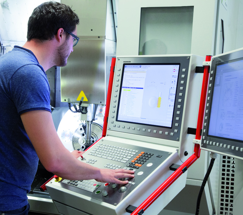
The TNC 640’s new graphics package includes a CAD viewer that opens any *.Step, *.Iges and *.Dxf file, and allows an operator to evaluate the workpiece at the control. For the machine builder, DCM (Dynamic Collision Monitoring) is available on the TNC. For this, HEIDENHAIN created a M3D converter. Through this powerful PC tool, CAD files of components in the machining envelope can be merged, edited and added to the Collision Monitoring.  

And when the new interpolation turning feature is in use with a TNC 640, the associated machine tool’s linear axes move along a circle, while the cutting edge with the milling spindle is always oriented to the center of rotation (outside machining) or away from the center of rotation (inside machining). Interpolation turning is especially well suited for manufacturing large, rotationally-symmetric sealing surfaces and, for example, for machining the housings of components of power plant technology (energy generation).

Another new feature is Cycle 880, for gear hobbing of external cylindrical and helical teeth. This machining process is performed through synchronization of the tool and lathe spindles. Furthermore, the cycle positions the rotary axis to the required tilting position and performs the infeed movements to the workpiece in the radial direction, and the milling movements in the axial direction.   

This machining process is for external cylindrical and helical teeth, and is performed through synchronization of the tool and lathe spindles.

Lastly, determining the 3-D basic rotation for a plane surface has been added as a manual probing function. The misalignment of a surface can be measured by probing three points in any direction on that plane. Subsequently, the result can be transferred to the datum table and/or the workpiece can be aligned.

Related Glossary Terms

  • 3-D

    3-D

    Way of displaying real-world objects in a natural way by showing depth, height and width. This system uses the X, Y and Z axes.

  • computer-aided design ( CAD)

    computer-aided design ( CAD)

    Product-design functions performed with the help of computers and special software.

  • gang cutting ( milling)

    gang cutting ( milling)

    Machining with several cutters mounted on a single arbor, generally for simultaneous cutting.

  • interpolation

    interpolation

    Process of generating a sufficient number of positioning commands for the servomotors driving the machine tool so the path of the tool closely approximates the ideal path. See CNC, computer numerical control; NC, numerical control.

  • lathe

    lathe

    Turning machine capable of sawing, milling, grinding, gear-cutting, drilling, reaming, boring, threading, facing, chamfering, grooving, knurling, spinning, parting, necking, taper-cutting, and cam- and eccentric-cutting, as well as step- and straight-turning. Comes in a variety of forms, ranging from manual to semiautomatic to fully automatic, with major types being engine lathes, turning and contouring lathes, turret lathes and numerical-control lathes. The engine lathe consists of a headstock and spindle, tailstock, bed, carriage (complete with apron) and cross slides. Features include gear- (speed) and feed-selector levers, toolpost, compound rest, lead screw and reversing lead screw, threading dial and rapid-traverse lever. Special lathe types include through-the-spindle, camshaft and crankshaft, brake drum and rotor, spinning and gun-barrel machines. Toolroom and bench lathes are used for precision work; the former for tool-and-die work and similar tasks, the latter for small workpieces (instruments, watches), normally without a power feed. Models are typically designated according to their “swing,” or the largest-diameter workpiece that can be rotated; bed length, or the distance between centers; and horsepower generated. See turning machine.

  • milling

    milling

    Machining operation in which metal or other material is removed by applying power to a rotating cutter. In vertical milling, the cutting tool is mounted vertically on the spindle. In horizontal milling, the cutting tool is mounted horizontally, either directly on the spindle or on an arbor. Horizontal milling is further broken down into conventional milling, where the cutter rotates opposite the direction of feed, or “up” into the workpiece; and climb milling, where the cutter rotates in the direction of feed, or “down” into the workpiece. Milling operations include plane or surface milling, endmilling, facemilling, angle milling, form milling and profiling.

  • turning

    turning

    Workpiece is held in a chuck, mounted on a face plate or secured between centers and rotated while a cutting tool, normally a single-point tool, is fed into it along its periphery or across its end or face. Takes the form of straight turning (cutting along the periphery of the workpiece); taper turning (creating a taper); step turning (turning different-size diameters on the same work); chamfering (beveling an edge or shoulder); facing (cutting on an end); turning threads (usually external but can be internal); roughing (high-volume metal removal); and finishing (final light cuts). Performed on lathes, turning centers, chucking machines, automatic screw machines and similar machines.

Sponsored Content