Verification Software for Additive Manufacturing
Verification Software for Additive Manufacturing
The manufacturing world is embracing 3D metal printing in a big way. GE Aviation is using it to print fuel nozzles, saving aircraft owners millions in operation costs annually per plane. Medical device companies use it to print patient-specific orthopedic implants and life-saving surgical instruments. These are just a few examples of the gigantic strides metal printing has made over the past decade, with countless more to come as the technology becomes increasingly mainstream.

The manufacturing world is embracing 3D metal printing in a big way. GE Aviation is using it to print fuel nozzles, saving aircraft owners millions in operation costs annually per plane. Medical device companies use it to print patient-specific orthopedic implants and life-saving surgical instruments. These are just a few examples of the gigantic strides metal printing has made over the past decade, with countless more to come as the technology becomes increasingly mainstream.
There's only one problem though: Despite its awesome capabilities, metal 3D printing requires secondary processing—machining or grinding—to remove any support structures used during the build process, and oftentimes needs additional machining to achieve the desired part accuracy and surface finish.
3D-Hybrid Solutions Inc. knows this. As its name implies, the company leverages a hybrid approach to 3D printing. By integrating metal printing technology with a CNC machine tool, it's possible to apply powdered metal or wire feedstock at rates of up to 20 lbs. per hour (in some applications), then machine the part to precise dimensions on the same machine. There's no need for secondary fixtures because internal holes and channels can be machined before being "closed up" during printing, part accuracy is improved, and processing times are substantially faster than with conventional 3D printers.
"Aside from the relatively slow build speeds, that's the biggest drawback with 3D printed metal," says 3D-Hybrid Solutions' Karl Hranka. "Secondary machining of some sort is almost always needed, and on larger workpieces such as molds and aerospace components, this can mean a lot of unnecessary production expense and lead time. In most cases, it makes good sense to do this machining while you're actually building the part in order to machine hard-to-reach features. By consolidating the two technologies, you can achieve broader capability and greatly reduce total capital investment costs and operating costs."
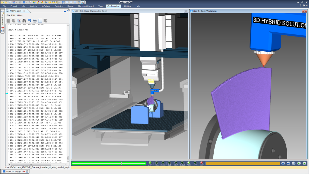
The risks in moving a five-axis deposition head around a workpiece whose geometry is continually changing are obvious. And being that many of 3D-Hybrid Solution's potential customers employ large, expensive machine tools, the need for a toolpath simulation and verification tool became abundantly clear. To address these concerns, 3D-Hybrid Solutions joined forces with CGTech, which earlier this year introduced a verification tool aimed specifically at additive manufacturers.
"Whether additive or subtractive machining, we consider ourselves experts in CNC machine kinematics, control technology, how the toolpaths and G codes interact on a machine. VERICUT simulates the same NC program that will drive the CNC machine, ensuring the highest level of verification possible," says Gene Granata, VERICUT product manager at CGTech. "This makes us a perfect fit in a hybrid machining situation. Not only can users check for the usual concerns like over-travels and tool collisions, but are also able to verify additive specific conditions—what's the layer thickness, how much stepover was used, and whether the proper gas and laser codes and settings are used to assure a robust build."
Some key points of the VERICUT solution include:
- Operators are able to "add-cut" or "cut-add" material, in any order and with any type of machining done, whether it's a 5-axis CNC machining center, multitasking turn-mill lathe, or deposition-style robot.
- As with all VERICUT products, the ability to accurately simulate the actual G codes provide users with the assurance that hybrid machine tools will be protected from expensive crashes, and avoid setups that "just don't work."
- Laser parameters and material deposition rates controlled directly by additive codes in the post-processed NC program are verified for proper additive functions and ranges.
- VERICUT provides a realistic view of additive material deposition—it's very easy to differentiate deposited "unfinished" material from previously machined features.
- Using VERICUT's AUTO-DIFF gouge check feature, voids and missing material are clearly visible, eliminating the chance for costly rework or potential part failures.
- Unique "droplet" technology provides programmers with detailed history of the build process and makes it easy to identify the exact source of problems via a single click, regardless of how many toolpaths or even setups are used to manufacture the part.
Both companies look forward to using their combined knowledge and technology to support customers. Granata says, "People are really catching on to what's possible with additive manufacturing, and the ability to machine parts and fabricate tooling in the same process brings that much more to the table. There's nobody else out there doing this level of validation or making the process look as realistic. It's going to make the technology much easier and safer for companies to adopt."


