VISI 2019 R1 Software
VISI 2019 R1 Software
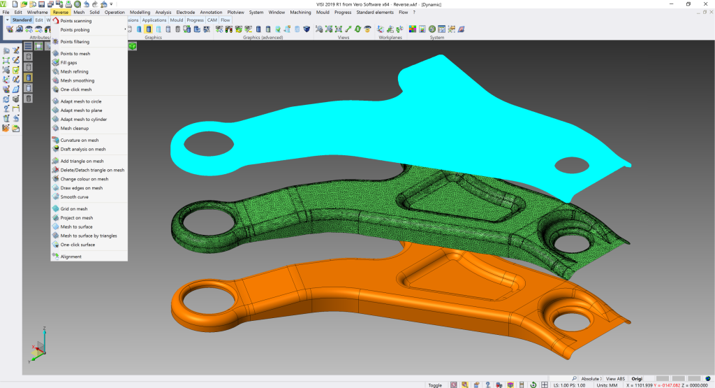
The latest release of VISI software includes a boost for reverse engineering, along with a range of new and enhanced CAD/CAM functions for the mold and die market. As part of a larger synergy project for reverse engineering and casting, VISI 2019 R1 introduces an extended direct interface to multiple portable measuring arms and Leica scanning devices from Hexagon. This, together with the enhanced dedicated module, provides a reverse engineering solution, as well as the ability to generate casting and stock models from VISI's existing modelling and machining environment.
The latest release of VISI software includes a boost for reverse engineering, along with a range of new and enhanced CAD/CAM functions for the mold and die market. As part of a larger synergy project for reverse engineering and casting, VISI 2019 R1 introduces an extended direct interface to multiple portable measuring arms and Leica scanning devices from Hexagon. This, together with the enhanced dedicated module, provides a reverse engineering solution, as well as the ability to generate casting and stock models from VISI's existing modelling and machining environment.
VISI Product Manager Marco Cafasso says it means that a points cloud can be loaded either directly or indirectly, and the relative mesh can be created by setting different options for refining and smoothing. "Also, surfaces can be created automatically or semi-automatically by extracting different key geometrical references from the refined mesh. And scan data, stock or reference casting mesh models can easily be aligned to the original geometrical CAD model using dedicated commands to allow comparisons, gap analysis and optimized toolpath processes."
The new ejector pin labelling functionality, which has been specifically produced for plastic mold designers, enables all the ejector pins in a mold design project to be identified in a table by a user-defined label. "This feature simplifies the maintenance process of the mold itself where one or more ejector pins need to be replaced. It easily identifies any ejector pin for maintenance purposes, and updates it if it needs replacing," Cafasso says.
VISI 2019 R1 introduces a function for advanced sketching of conformal cooling channels. It allows the use of wireframe circuits, previously created in CAD, along with selecting predefined or user sections, and automatically creates the conformal channels to form the desired cooling circuit. "It's also possible to edit those channels, even after subtraction from the mold insert," Cafasso says. "All the information defined on the conformal cooling during the design phase are automatically managed by VISI Flow's thermal analysis. And the Flow thermal analysis itself has also been enhanced to provide a graphical temperature display on a dynamic section on the inserts." The result is a simplified process and time saving of the mold design and Flow analysis.
The blanking process has been enhanced, to set the faces on the model affected by the pressure pad, by simply defining the relative force to apply. This allows the material to flow, based on the applied force on the pressure pad.
Cafasso says users can also set constraints to simulate the effect of a uniformly distributed blank holder force. "In fact, it's possible to define a friction value and the force value to be applied for the blanking phase. This leads to a more accurate blanking process, which gives additional support to the user during the design phase of the die."