Cartridges for a modern shop
When using indexable inserts, employ fine adjustment cartridges made for the 21st century.
Cartridges to hold indexable inserts in cutting tools have been used for many years. In modern manufacturing environments, cartridges have a permanent place in tools for boring, turning, milling and drilling. Cartridges became popular on shop floors for many reasons:
- Cartridges allow tool adjustability when a more accurate insert location is required. As a separate component, a cartridge can be accurately moved independently from other cutting elements of the tool to compensate for imperfections in the manufacturing process.
- Cartridges protect expensive cutter bodies. Collisions are a typical failure mode in a cutting operation. Even with the improved verification environment of modern CAD/CAM systems, as well as employing tool monitoring systems, there is a high chance of a collision between the cutting part of the tool and the workpiece. Positioning of cartridges is done so that they take all “abuse” and protect the body from severe damage.
- Cartridges reduce tooling costs by using standard components produced by multiple vendors on the open market.
- Cartridges improve the quality of cutting tools by using premium alloy steels with appropriate heat treatment to allow softer and lightweight materials for tool bodies.
- Cartridges enable users to build multiple stations on a tool to combine many different operations in a single path. This capability plays an important role in increasing the material removal rate, especially in mass production.
The main standard describing types and sizes of cartridges, ISO 5611 (cartridges, type A, for indexable inserts — dimensions), had a major update in 2015 and now consists of 12 substandards, from ISO 5611-1:2015 to ISO 5611-12:2015. Historically, this evolved from German standard DIN 4985.
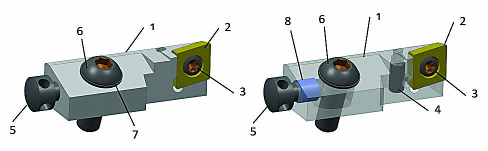
Figure 1: The typical cartridge design per ISO 5611 is displayed
The typical design of an ISO 5611 cartridge (see Figure 1) includes 1) a solid body made from heat-treated alloy steel; 2) a cutting insert fabricated from carbide, ceramic or superhard cutting materials like PCD or CBN; 3) an insert retaining screw; 4) a radial adjustment screw; 5) an axial adjustment screw; 6) a cartridge clamping screw; 7) a washer; and 8) an optional thread retaining element, or helicoil.
The standard itself does not dictate cartridge design but only the main dimensions. Over time, however, different manufacturers unified to create a principal design, and this is why all cartridges look alike today.
Over the past three decades, manufacturers have significantly improved the design and performance of machine tools. Spindles have become faster and more rigid. Accuracy has become higher. Communications and data acquisition systems have increased machine efficiency and output. Many breakthroughs similarly were made in the development of new carbide grades and superhard cutting materials. But cutting tool designs — particularly with ISO cartridges — are lagging behind this progress in the rest of the industry.
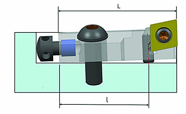
Figure 2: The usual installation of the cartridge per ISO 5611
Several factors are especially outdated (see Figure 2) and take away from machine tool achievements:
- Using standard socket setscrews with a large pitch of thread creates adjustment resolution that is below that of modern demands. For example, for the cartridge 10CA (10 = distance to the cutting edge in millimeters; C for cartridge; A for type A), the diameter of the screw thread is M4 mm, and the pitch is equal to 0.7 mm. This means that to complete one revolution of the screw, the cartridge will move radially 0.7 mm.
- The ratio of L/l>>1 reduces the resolution of adjustment even further.
- Due to the rigid body of the cartridge, adjustment is possible only by stretching clamping screw 6. (See Figure 1.) Practically, smaller screw 4 is working against larger screw 6. (See Figure 1.)
- There is no firm body support under the application of the cutting force because of clearance between the cartridge body and pocket floor.
These drawbacks lead to a cumbersome adjustment process that requires multiple repetitions. To make an adjustment, an operator usually applies reduced torque to clamping screw 6. (See Figure 1.) Then, he or she actuates adjustment screw 4 and secures clamping screw 6 to the necessary specification. During this process, the cartridge body slightly deforms and the target position of the insert changes. From this point on, everything depends on operator experience. Some operators start over again by releasing the clamping screw while others use a radial screw to fine-tune the position of the cutting edge. It’s impossible to predict how hard the radial adjustment screw will be jammed by the clamping screw. The size of the hex or Torx tool driving the screw is small and may be insufficient to overcome the friction.
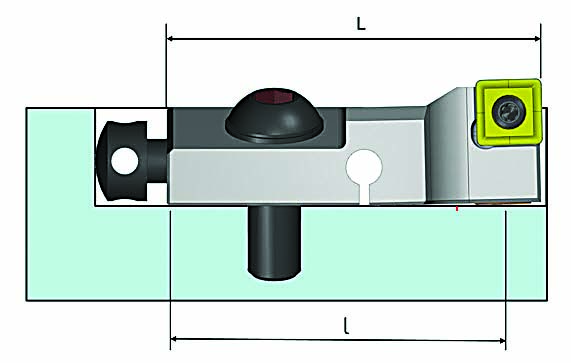
Figure 3: The new concept of the fine adjustment cartridge is detailed. (Fr is radial cutting force.) Figures courtesy of Sandvik Cormorant” data-entity-type=”file” data-entity-uuid=”4b7de230-44da-429e-b3d6-33727615653f” height=”220″ src=”/wp-content/uploads/legacy/inline-images/Fig.3.jpg” width=”620″ />To address the shortcomings of the traditional design, Sandvik Coromant Co. developed a cartridge concept (see Figure 3) that realigned a new cartridge with advances achieved in machine tools.This new cartridge is built on the flexible body 1 platform as shown in Figure 3. Insert 2 is secured by screw 3 in the front part of the cartridge. Clamping screw 6 with washer 7 and thread retainer 8 are similar to the original design. The game changer is the incorporated differential screw 4 pared with push pad 9. Both threads on the differential screw are made of the same lead but different pitch. For example, one thread can be M4 mm and the other M4.25 mm. This makes the resulting pitch 0.25 mm, which is much smaller than a traditional design (0.7 mm).In addition, radial adjustment screw 4 is positioned on an angle α = 60 degrees to refine the resolution of adjustment even more. The actual resolution of adjustment in 10CA cartridges is 0.019 mm (0.0007″) per 90 degrees of rotation of the adjustment screw. In practical application, an operator can dependably adjust the position of the cutting edge with an accuracy of up to 0.001 mm (0.00004″).Another benefit of the push pad is strong support in the area where the radial vector of the cutting force (Fr) has the highest impact and reduced ratio L/l. (See Figure 4.)Figure 4: The normal installation of the improved cartridge is presented.
A quintessential feature of this design is the flexible body of the cartridge, which is created by recess 10. (See Figure 3.) It requires and allows constant pre-loading between cartridges and the host cutting tool. One positive effect of this is zero backlash in the differential couple and, as a result, smooth adjustment in both directions: up and down. There is also no need to release the cartridge clamping screw when performing an adjustment. This dramatically reduces maintenance time and makes the tool much more user-friendly.
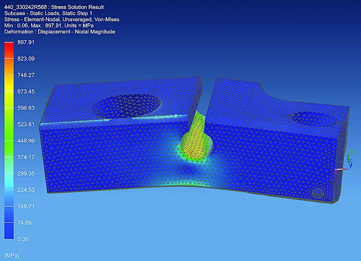
Figure 5: Von Mises stress is shown in the recess area at maximum deformation.
When nominal pre-load in the cartridge body was calculated, Sandvik Coromant took into consideration the following factors:
- Additional maximum deformation of 0.2 mm (0.008″) for compensation of the cutting edge wear.
- The effect of centrifugal force for high-speed applications — for example, machining of aluminum with PCD inserts.
- Maximum stress in the critical cross section of the body. (See Figure 5.)
Maximum additional deformation of the cartridge front part is necessary to compensate for dimensional wear of the cutting edge for the duration of the complete operation. The intent of the design was to stay within the linear range of deformation and prevent fatigue failure. After the worn insert is indexed and the cartridge is adjusted to nominal dimension, stress is automatically reduced to the nominal.
In the case of high-speed machining, the front part of the cartridge harnesses centrifugal force in accordance with equation (1):
Review the print ads from this magazine to continue
This quick advertiser review unlocks the rest of the article and keeps the full-screen reader focused on the ads instead of the page chrome.