Straight to a round
Parts manufacturers should head straight to their high-strength round inserts to turn nickel-base alloys.
Parts manufacturers should head straight to their high-strength round inserts to turn nickel-base alloys.
Parts used in extreme conditions require extreme materials. The part may be a large ring or shroud in a jet engine, which operates at up to 1,200° F, or can be a down-hole component in an oil field, operating in a corrosive environment hundreds of feet underground.
So aerospace and oil and gas companies have many of their parts made from nickel-base alloys (heat-resistant superalloys). To turn these materials, which include Inconel, Hastelloy, Waspaloy and Monel, manufacturers should have their eyes firmly fixed on that humble cutting tool, the round insert.
Round inserts may be underutilized in some manufacturing sectors, but the aerospace and oil and gas industries shouldn’t be among them.
No Cutting Corners
Despite some major advantages, round inserts may be unattractive to manufacturers for several reasons. One is they can’t machine small-radius corners. For example, a 0.5 “-dia. round insert can’t turn a 90° corner with a radius of 0.004 “. Its smallest corner radius is 0.5”.
The tool’s inability to create small-radius corners leads many parts manufacturers, and their programmers, to apply other insert shapes. “The CNMG is pretty much the first choice for any programmer because of the combination of flexibility and edge strength,” said Bill Tisdall, development specialist manager for toolmaker Sandvik Coromant Co., Fair Lawn, N.J. “You can OD turn, you can face, you can out-copy, you can turn to a square shoulder. With a round insert, you can’t turn to a shoulder. You can do all the other things.” (Out-copying is machine movement that combines a Z-axis movement toward the chuck with an X-axis movement away from the center line of the workpiece.)
Moreover, round inserts aren’t well suited to machining complicated profiles, like undercuts, and can’t create profiles not present in their geometry, according to Don Graham, manager of turning products for toolmaker Seco Tools Inc., Troy, Mich.
Finally, a round insert can more easily damage a workpiece than a straight-edged insert. A round insert has a relatively large radius compared with a straight-edged insert, which has small radii at its corners. A large radius means more contact surface, which results in higher cutting forces. “This can be detrimental when applied in weak setups, extended tooling or on workpiece features that have a thin cross section,” said Dale Hill, applications engineer for toolmaker Greenleaf Corp., Saegertown, Pa. Detrimental effects include workpiece deflection and vibration.
Consequently, parts manufacturers have to maximize machine tool and workholding rigidity if they want to successfully apply round inserts.
Reasons to be Round
Round inserts can be worthwhile, though, because they’re strong and can be fed at higher rates than other types of inserts, more than making up for their disadvantages in certain applications.
Time saved via higher feed rates means money saved. “The amount of money you can save [by using round inserts] over the life of running an insert is phenomenal,” Tisdall said, adding that actual cost savings depend on a shop’s overhead, annual number of components and reduction of a part number’s process time.
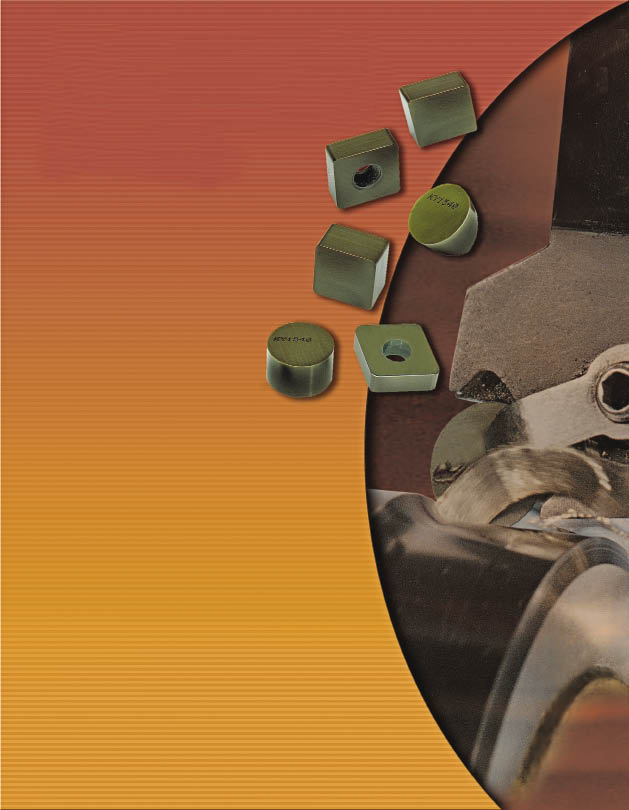
Courtesy of Kennametal
Workholders and machine tools must be rigid to apply round inserts because the tool’s radius, relatively large compared with a straight-edged insert, means more contact area and therefore more cutting pressure.
Graham estimated that round inserts can be fed 20 percent faster than other types of inserts, depending on the round tool’s chipbreaker, which can be designed for different feed rates. Graham cited a chipbreaker with a neutral land and relatively wide groove as an example, saying that a round insert can take a heavier feed rate than one with a positive rake and narrow groove width. (See recommended feeds and speeds chart on page 39.)
Round inserts can operate at higher feed rates because they have the strongest geometry. “The larger the included angle of the cutting edge, the more inherent strength you have in that insert,” said Frank Battaglia, staff engineer–global machining technology with Kennametal Inc., Latrobe, Pa.
He compared inserts’ different included angles; the 100°, 90°, 80° and 60° corners of various inserts, all the way down to a VNG-insert, which has a 35° angle. “The cross-sectional area, going from one side of that insert to the other, gets smaller and smaller as you go down in that angle,” Battaglia said. “With a round insert, it’s really just maximized to the point where you have the largest cross-sectional area going across from one side of the cutting edge to the other side.”
“There’s more material behind the force in a round insert, more material to absorb the force,” Graham added.
Their greater strength makes round inserts excellent at rough turning the scale present on forged and cast workpieces. Their strength also makes them less prone to chipping and breakage than other types of inserts.
Moreover, their strength and related long life mean round inserts are well suited to turning the large workpieces often manufactured by aerospace and oil and gas companies. “The round insert provides the best tool life and strength of any shape of an insert, so when you have a very large length of cut, you’re able to machine that full length with a round insert,” said Sandvik Coromant’s Tisdall. “With an angled insert, you’re typically going to get less tool life. You’d have to index the tool midcut.”
“Typically in aerospace, they will produce massive forgings,” Graham said. A 40 “-dia. ring that’s 0.5 ” thick × 2 ” wide may have started as a 48 “-dia. ring with a 6 ” thickness and a 6 ” width. “They remove massive amounts of material to produce that ring. That’s where a round insert is very useful because you can hog out a lot of material in an aggressive fashion,” Graham said.
Going Negative or Positive?
A parts manufacturer has to consider whether to apply a round insert with a negative geometry, a neutral one or a positive one for machining a nickel-base alloy.
According to Graham, producers of parts for oil and gas applications typically prefer negative or neutral rake angles on their round inserts because the angles provide extra strength. Those companies also like the inserts to have strong, heavy chip grooves.
Courtesy of Sandvik Coromant
A round insert can be fed up to 20 percent faster into a workpiece than other types of inserts because the tool has the strongest geometry of any insert shape.
Greenleaf’s Hill added that a negative rake angle is particularly suitable for interrupted turning. “When it engages the workpiece, the majority of that chip or swarf impacts that top surface of the insert, which is the strongest area of that cutting tool,” he said. “So, in interrupted turning you’re now presenting the strongest area of your cutting tool to that abusive situation.”
However, a negative rake angle tends to create greater cutting force, which may not be right for a particular application. Hill recommends the correct geometry for the job. “Use negative whenever possible for strength and economy—negative tools are generally double sided, allowing for more cutting edges. Use positive geometry if surface finish, tool force or built-up edge is a concern.”
Martin Gardner, global product manager—turning, threading and grooving for toolmaker ATI Stellram, La Vergne, Tenn., agreed. He suggested an RCMT insert, which has a 7° rake angle, for this application. “That’s probably the most popular insert we see in these types of applications,” he said. “They’re used for profiling and for narrow grooves.”
He also said round inserts need an edge hone that’s not too large because that would create too much cutting force.
Recommended speeds and feeds for turning nickel-base, heat-resistant superalloys.
| Machining stage | 1st grade choice | 2nd grade choice | Cutting speed (sfm) | Feed (ipr) | DOC (in.) | Insert style | Metal-removal rate (in.3/min.) | Comments |
| First |
CC670 |
CC6065 |
500 to 656 |
0.006 to 0.008 |
Up to 0.197 |
RNG 6 |
12.20 |
Use 45° approach to reduce chip thickness and notching—first choice on good-quality forgings. |
| Intermediate |
CC6060 |
CC6065 |
656 to 984 |
0.004 to 0.008 |
0.040 to 0.118 |
RNG 4 |
7.32 |
Use round inserts wherever possible to minimize notching. |
|
CC6060 |
CC6065 |
656 to 820 |
0.004 to 0.008 |
0.040 to 0.118 |
RPGX |
4.88 |
For pocketing, use positive inserts. Finish task to continue reading
Review the print ads from this magazine to continueThis quick advertiser review unlocks the rest of the article and keeps the full-screen reader focused on the ads instead of the page chrome. Task complete
Continue readingThanks for supporting the advertisers that help keep the magazine moving. Continue reading below.
May 2009
May 2009 |


MFGAxis Discussion