The impeller–quintessential example of 5-axis machining
March 2009 Get With The Program column
Few 5-axis machine users ever cut an impeller. Yet impellers are repeatedly used as examples by CAD/CAM software vendors and machine tool builders. There is a practical reason for this. Impellers have challenging shapes that ably demonstrate 5-axis capabilities.
Because the impeller offers so many 5-axis challenges, I will use one as an example to explain common 5-axis machining issues. Even if you don’t cut impellers, this information likely applies to some aspects of your multiaxis machining.
Courtesy of CNC Software
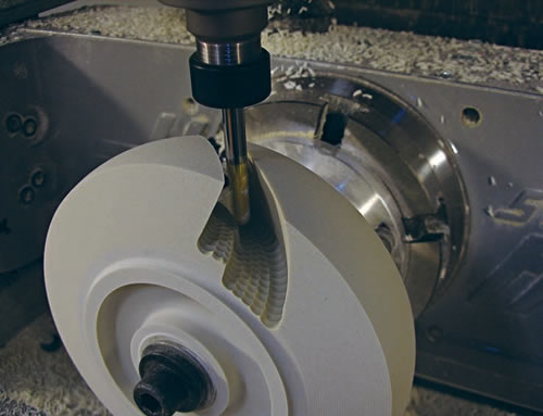
When 5-axis plunge roughing, tool deflection is minimal because cutting forces are aligned with the cutter’s center axis, dramatically extending tool life.
In the early ’70s before CAD/CAM systems, the design of an impeller’s individual blades, or vanes, was based on projected, synchronized and smooth machine motions. Those pure designs where perfectly suited for swarf 5-axis tool motions, where it was possible to cut the blades with the side of a tool, usually a straight or bull nose corner-radius cutter. (Swarf refers to the tilted or twisted blade wall surfaces that are cut with the side of a tool.)
The design of modern impeller blades is not as pure. They are often designed with solid-modeling CAD packages, allowing the user to create shapes that are highly complex but may have a total disregard for manufacturing efficiency.
Most of the blades are tall on one end, usually near an impeller’s center, and short on the other. Modern blades are often “warped,” making swarf cutting impossible because they have to be cut in multiple steps with the nose of a tapered ballnose cutter, as the tool axis is manipulated to avoid collisions.
Machining impellers from a blank involves turning, roughing the excess material from between the blades, semifinishing the floor and the blades and then finishing the floor and the blades. If a multitasking machine is available, these operations can be done in one or, possibly, two setups.
It is common practice to rough the excess material from between the blades using 3+2 machining techniques. This is done by indexing the rotary axes, locking them in place to keep the 5-axis machine in its most rigid state and then attacking the exposed excess material using simple 3-axis toolpaths. The drawback of this approach is that it is not always possible to remove all the excess material. It is hard to keep track of in-process material and it is necessary to overlap between cuts—causing too many “air” cuts. Furthermore, the area between the blades is often deep and narrow—a bad combination because it requires long, skinny tools. These tools don’t do well side-cutting, especially when the cutting pressures constantly change, causing variable amounts of deflection. This in turn causes vibration, shortens tool life and imparts a poor finish.
Review the print ads from this magazine to continue
This quick advertiser review unlocks the rest of the article and keeps the full-screen reader focused on the ads instead of the page chrome.


MFGAxis Discussion