Wheels Up: 5-Axis Machining
New materials, the need for lightweight parts and the burgeoning size of some aircraft challenge manufacturers of landing gear components.
New materials, the need for lightweight parts and the burgeoning size of some aircraft challenge manufacturers of landing gear components.
Sleek wings and powerful engines are familiar images of flight. An aircraft’s landing gear, however, is just as essential for successful air travel. A fully loaded, double-deck, 800-passenger Airbus A380 jetliner weighs about 1.3 million lbs. Aloft, those 650 tons are supported by the magic of aerodynamic lift. But movement on the ground, including takeoff and landing, are handled by components that are complex, remarkably strong and quite large.
For example, Goodrich Corp., Charlotte, N.C., said the undercarriages for the main landing gear it supplies for the A380 are 18½ ‘ tall. As the size of some aircraft grows and demand for fuel efficiency increases across the board, manufacturers of landing gear face the challenge of making the large, complex assemblies both as strong and as light as possible.
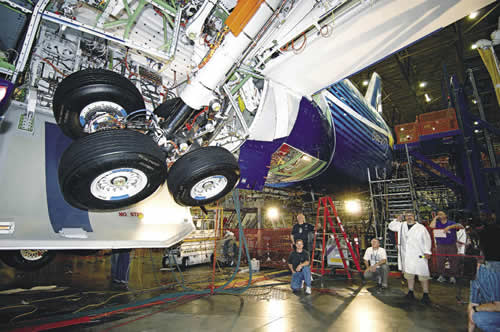
Courtesy of Boeing
A landing gear test on the Boeing 787 Dreamliner.
Like all manufacturers, landing gear makers are dealing with supplier consolidation and implementation of lean initiatives. Said John Cerps, manufacturing engineering manager at the Toronto facility of global landing gear provider Messier-Dowty International, Vélizy, France, “over the last 5 to 10 years, there has been a major transition for all major subsystem suppliers to airframe manufacturers. Everyone is trying to offer an integrated system as opposed to individual parts or subassemblies.”
Cerps said Messier-Dowty Inc. works with its customers to determine the space available for the landing gear, the desired configuration and functional details, and then provides a plug-in solution. “We are giving them the landing gear system,” Cerps said, “which is all the electrics, hydraulics and pneumatics, complete with wheels, brakes and tires, the steering system and braking system. The landing gear is bolted into the aircraft and all they have to do is connect the electrics, hydraulics and pneumatics.”
Cerps estimates that the Toronto facility, whose capabilities include design, development, production and support of landing gear for military, business and commercial aircraft, manufactures about 10 percent of the parts for the systems it provides. For the rest, it relies on a network of proven suppliers. Cerps said his facility machines “all of the parts that are very complex, which require an investment in specialized machine tools.”
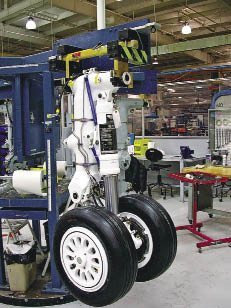
Courtesy of Messier-Dowty
This business jet’s main landing gear is typical of the integrated landing gear systems provided by Messier-Dowty.
Also like other manufacturers, Messier-Dowty is “in competition with ourselves; we are mandated by our corporate head offices to continually improve,” Cerps said. For example, he described efforts to optimize production of a family of landing gear components consisting of four pistons and four cylinders. Based on lean manufacturing principles, Messier-Dowty created an autonomous cell consisting of two lathes, a 3-spindle vertical machining center with an automatic 4th-axis indexing fixture and a 3½-axis horizontal machining center. “One of the flatbed lathes was set up for external work and the other was set up for internal work,” Cerps said, who added that the arrangement greatly reduced setup time because the machines didn’t have to be reconfigured individually to handle those operations. “The guys in the cell received cross training, employed pull systems and followed all the rules of Kanban,” he added. In addition to speeding throughput, the work also helped assure part-to-part consistency by simplifying machine-to-machine transition of the parts.
The basic elements of an aircraft landing gear are the major support component, called the main or center fitting; the piston, or slide, that goes into the center fitting and provides the ability to lower and raise the gear; and the truck, or bogie beam, which is the crosspiece through which the axles run. The assembly also includes various small support struts, linkages and actuators. Until recently, ultrahigh-strength steels (such as 300-M, a high-tensile modified 4340 alloy) and aluminum alloys were the main materials employed. Now, to meet fuel economy-driven weight reduction requirements while maintaining strength, titanium and composites are being introduced. For example, the Boeing 787’s main landing gear, produced by Messier-Dowty, includes ultrahigh-strength steel components, a titanium slider and braces made of composites. Messier-Dowty said it evaluated the manufacture of landing gear components from titanium matrix composites. Those materials exceed the performance of 300-M steel and titanium through a combination of strength, durability and light weight, but high material and manufacturing costs presently exclude their application.
Simultaneous Strategy
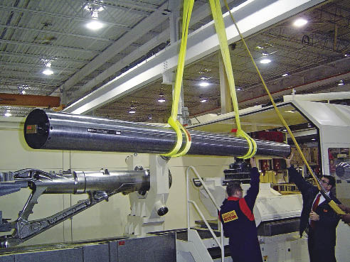
The time required to machine landing gear components, especially large parts, is remarkable. Mike Zambenedetti, senior application engineer for machining systems supplier MAG Cincinnati, Hebron, Ky., said a typical large landing gear component can be 150 ” long and require processing on a series of five to 10 different machine tools. The high-strength alloy steel and titanium parts begin as rough forgings and machining times for each part are lengthy: total OD roughing can consume 200 hours, finishing can add 240 hours and ID operations may take 200 hours.
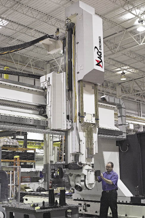
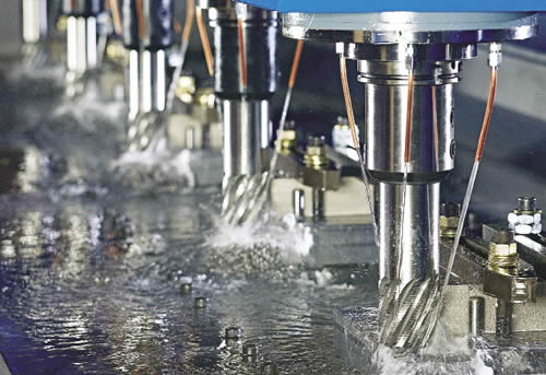
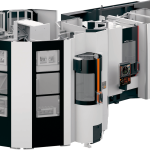
Courtesy of MAG Cincinnati
Top: A technician performs maintenance on a U5 single-spindle, 5-axis machining center from MAG Cincinnati. This configuration provides the flexibility and Z-stroke capacity required to access certain features on landing gear components.
Below: A titanium aircraft landing gear bogie beam fixtured for finishing operations in a U5 single-spindle, 5-axis machining center.
Mike Sess, MAG application engineering and vertical machine platform manager, said a key to maximizing throughput of the large parts is simultaneous machining. To facilitate that, MAG supplies multispindle, multiaxis profiling machines in which the spindles follow identical paths. In a 5-axis, 5-spindle profiler, for example, all five spindles move on the same X, Y, Z, A and B axes. “They are all carried in the same ‘bathtub,’ as we call it,” Sess said. The spindles are programmed to work on five identical parts simultaneously, reducing the total time required to perform an operation on the parts by 80 percent compared to a single-spindle arrangement.
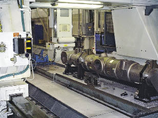
Courtesy of MAG Cincinnati
In a 5-axis, 5-spindle profiler supplied by MAG Cincinnati, all five spindles move on the same X, Y, Z, A and B axes, follow identical paths and are programmed to work on five identical parts simultaneously.
The machines optimize workhandling as well. A 5-spindle profiler can feature an X-axis stroke of 144 ‘, which, according to Zambenedetti, enables the manufacturer to set up zones where parts can be loaded or unloaded while other parts are being machined.
Illustrating the aerospace industry’s demand for such machine tools, MAG Cincinnati is scheduled to deliver $70 million of equipment to the world’s largest producer of titanium, VSMPO-Avisma, for a global “Landing Gear Manufacturing Center for Excellence” in Verkhnaya Salda, Russia. The order includes four multispindle titanium profilers and 12 HMCs, as well as workhandling and control equipment. The facility will produce landing gear components for the Boeing 787 and 777, the Airbus A380 and A350WXB and the Sukhoi Superjet 100. MAG Cincinnati’s shipment follows its delivery of 10 titanium machining systems to VSMPO and its neighboring Boeing joint-venture company, Ural Boeing Manufacturing.
The size and capability of aerospace machining systems have evolved in tandem with changes in aircraft components, Sess said. In a response to growing use of titanium alloys for landing gears, enhancements to MAG profilers include spindles with torque output in the range of 2,000 lbs.-ft., application of the heavy-duty HSK 125 toolholders and design features that increase the machines’ stiffness and rigidity.
As for smaller landing gear components, they benefit from mill/turn centers. Although those machine tools generally possess a smaller swing capacity than massive single-purpose equipment and therefore are limited to smaller parts, the centers reduce setup times “drastically because you can do multiple operations in one setup,” said Peter Bhavra, tooling engineering specialist at Messier-Dowty in Toronto. Bhavra said the facility is adding two multitask machines to the mill/turn equipment it already has and plans to move currently produced parts to the new machines to optimize production and further improve consistency of part quality.
Tooling Package
Chris Mills, U.S. senior project manager of aerospace development for toolmaker Sandvik Coromant Co., Fair Lawn, N.J., said the unique features of and materials for landing gear components has prompted development of specialized aerospace tooling. For example, he said, Sandvik Coromant has assembled a package of tools for the key operations in landing gear machining, including deep-hole drilling, external profiling, 2-D and 3-D turn/milling, trepanning and helical interpolation. When manufacturing landing gear components from forgings, he said, “there is a huge amount of material that is removed,” adding that when machining is completed, often just 10 to 20 percent of the forging’s original weight remains.
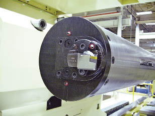
Mills said perhaps the most challenging operation is drilling deep, large-diameter holes. “Some of the holes down the middle of a component are over 1 ‘ in diameter and 6 ‘ in depth.”
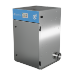
Courtesy of Sandvik Coromant
For deep-hole drilling operations on large landing gear components, Sandvik Coromant developed T-Max special drill heads for diameters from 100mm to 358mm. The heads are designed to work with high-pressure, high-volume coolant systems. To facilitate chip removal in deep bores, the coolant is routed to the cutting drill’s cutting edges and then flows back through the drill body itself.
For large landing gear components, deep-hole drilling often is performed on specialized machines. To make deep holes with the special machines, Mills said Sandvik Coromant developed T-Max special drill heads for diameters from 100mm to 358mm. Exchangeable cartridges and shims enable the head to be adjusted to produce different diameters.
The heads work with high-pressure, high-volume coolant systems. Unlike the coolant path in a typical through-coolant tool, in which coolant flows through the drill tip and out of the hole past the outside of the drill shaft, in the big drilling heads the coolant is routed to the cutting drill’s cutting edges and then flows back through the drill body itself to enhance chip removal from deep holes. To maintain concentricity, wear pads are situated on the drill’s OD. The tendency of titanium to chemically combine with cutting tool materials dictates the wear pad design and compositions. “The wear pads need to be smooth, have good lubricity, and not have reaction at all with the material,” Mills said.
Courtesy of Sandvik Coromant
Review the print ads from this magazine to continue
This quick advertiser review unlocks the rest of the article and keeps the full-screen reader focused on the ads instead of the page chrome.


MFGAxis Discussion