



The basics of servomotor axis control
The Machine Technology column in the July 2011 issue of Cutting Tool Engineering magazine takes a look at how the precise control of axis position works.
Precise control of axis position is an enabling technology for automatic machine tools. How does it work?
Several ways exist to control axis position, but one of the easiest to understand is a permanent-magnet DC servomotor. The basic element is a DC motor, in which there are loops of wire on an armature that is free to rotate on bearings. The armature is in the presence of a magnetic field created by permanent magnets. When a voltage is applied to one of the loops, a torque is created, which causes the armature to rotate (Figure 1).
As the armature rotates, the torque decreases, but then the voltage is switched to the next loop of wire. The contacts between the loops of wire and the voltage source are maintained by conductive brushes, and the switching between loops is called “commutation.” The rotating armature of the DC motor is connected to a screw. As the screw rotates, it drives a nut attached to the machine tool table, causing the table to slide along the guide way.
The torque created by the applied voltage is used to accelerate the inertia of the motor and screw, and to overcome the friction and load torques. A DC motor in this configuration—called “open loop”—has a rotational speed that is sensitive to the load torque. It directly “sees” the inertia of the rotating armature and screw and the friction in the bearings. It also sees the table mass and the cutting forces, but only indirectly through the screw.
To make the DC motor less load sensitive, it is common to measure the rotational speed, compare it to the desired speed and adjust the command voltage to the DC motor based on the difference. The rotational speed of the motor can be measured with a small generator attached to the rotating shaft. This is called a “tachogenerator.” The tachogenerator produces a voltage proportional to the rotational speed of the shaft; it is like a DC motor, but backwards.
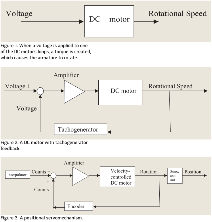
The measured voltage is compared to the input voltage, and the small difference is amplified and passed to the DC motor (Figure 2). In this configuration, the DC motor has a velocity feedback and is said to be under velocity control. This trick makes the DC motor much less sensitive to the external load.
View print ads from this spread
Review the ads on this magazine spread to continue reading. Each ad takes two seconds; a two-page ad counts once.
Advertisers on this magazine spread
Print placements on this magazine spread
Schutteusa
friction and load torques. A DC motor in a DC motor, but backwards. to be under velocity control. This trick
this configuration—called “open loop”— The measured voltage is compared to makes the DC motor much less sensitive has a rotational speed that is sensitive to the input voltage, and the small difference to the external load. the load torque. It directly “sees” the in- is amplified and passed to the DC motor End users obviously want to con-.
friction and load torques. A DC motor in a DC motor, but backwards. to be under velocity control. This trick this configuration—called “open loop”— The measured voltage is compared to makes the DC motor much less sensitive has a rotational speed that is sensitive to the input voltage, and the small difference to the external load. the load torque. It directly “sees” the in- is amplified and passed to the DC motor End users obviously want to con- ertia of the rotating armature and screw (Figure 2). In this configuration, the DC trol axis position in a machine tool— and the friction in the bearings. It also motor has a velocity feedback and is said not just speed. They need a device to sees the table mass and the cutting forces, but only indirectly through the screw. To make the DC motor less load sen- sitive, it is common to measure the ro-
Visit Schutteusa View this placement in the issue recordPrint ads from this magazine
this configuration—called “open loop”— The measured voltage is compared to makes the DC motor much less sensitive has a rotational speed that is sensitive to the input voltage, and the small difference to the external load. the load torque. It directly “sees” the in- is amplified and passed to the DC motor End users obviously want to con-.
friction and load torques. A DC motor in a DC motor, but backwards. to be under velocity control. This trick this configuration—called “open loop”— The measured voltage is compared to makes the DC motor much less sensitive has a rotational speed that is sensitive to the input voltage, and the small difference to the external load. the load torque. It directly “sees” the in- is amplified and passed to the DC motor End users obviously want to con- ertia of the rotating armature and screw (Figure 2). In this configuration, the DC trol axis position in a machine tool— and the friction in the bearings. It also motor has a velocity feedback and is said not just speed. They need a device to sees the table mass and the cutting forces, but only indirectly through the screw. To make the DC motor less load sen- sitive, it is common to measure the ro-
Continue reading
July 2011
End users obviously want to control axis position in a machine tool—not just speed. They need a device to measure position, and also feed that back to compare against the commanded position. A common device for this purpose is a rotary encoder. One design consists of two transparent discs with some radial lines marked on them, a light source and a light sensor. One disc rotates with the DC motor armature, and one does not.
The light shines through the discs, and lots of light gets through when the lines are aligned, and the light sensor sees a bright signal. When the lines are not aligned, much of the light is blocked, and the sensor sees a dark signal. As the shaft rotates, the sensor sees a series of bright and then dark pulses, which indicate table position.
The commanded table position is also converted into pulses, or “counts,” by a piece of software called “the interpolator.” Based on a desired position and the linear velocity of the table, the interpolator spits out counts at a certain rate. The counts from the encoder are subtracted as the table moves toward the desired position. A DC motor in this configuration is said to be under positional control, or is called a “positional servomechanism.” The difference between the desired and actual position—the “to go” distance—is converted into a voltage, which is fed from the outer position loop to the inner velocity loop (Figure 3).
There are many design considerations and variations of this concept. For example, if the amplifier is more powerful, then positioning of the axis is less sensitive to loads and disturbances. However, if the amplification is too high, the control loop becomes unstable, similar to feedback in a microphone, and the axis will vibrate back and forth.
 It is interesting to note that for the axis to move, there must be an error in position. The difference between the commanded and actual positions creates the voltage that causes the motor to move. CTE
About the Author: Dr. Scott Smith is a professor and chair of the Department of Mechanical Engineering at the William States Lee College of Engineering, University of North Carolina at Charlotte, specializing in machine tool structural dynamics. Contact him via e-mail at kssmith@uncc.edu.
Glossary terms in this article
Related




Subscribers can use MFGAxis notes, saves and discussion tools with their innoNET account.


