Saving face: Get a grip on machined parts with face drivers
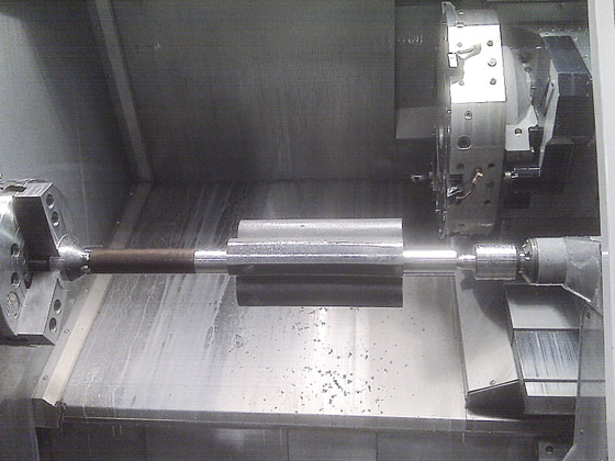
When turning long parts, the traditional workholding technique is to chuck one end of the part and support the other end with a live or dead center.
When turning long parts, the traditional workholding technique is to chuck one end of the part and support the other end with a live or dead center. This is generally effective but has two drawbacks. First, the part must be reversed (double-ended) to machine the end gripped by the chuck jaws, and, even when expertly done, rechucking can lead to taper and diminished concentricity in the part. Second, the time associated with double-ending and changing chuck jaws increases machine downtime, particularly when small batches with differing diameters require frequent setups.
All images courtesy Riten Industries
Face driving is a viable alternative when these drawbacks have a noticeable effect on production efficiency. Rather than clamping onto a surface to be machined, a face driver locates on the end face of the part. Chisel-edged drive pins penetrate the end face while a center point locates the part on center. The single-axis reference point established by the center point allows for a high degree of accuracy. By machining the entire surface in a single operation between centers, concentricities as accurate as 0.0004″ to 0.0008″ (0.0102mm to 0.0203mm) TIR are possible.
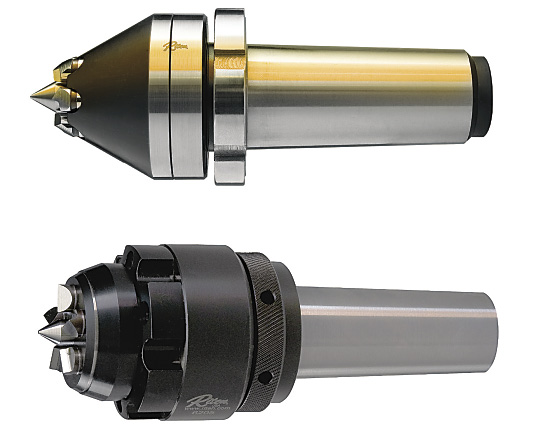
Figure 1. Mechanical face drivers allow quick changeout of drive pins and center points and deliver accuracies from 0.0004″ to 0.0008″ TIR. Hydraulic designs are better suited to roughing applications because their accuracies are from 0.0015″ to 0.0024″ TIR.
Face drivers are suitable for many between-center operations, including hobbing, milling, shaping, gear cutting, spline milling, facing, turning and grinding. Drivers are offered in two styles: mechanical and hydraulic (Figure 1).
Direct or Soft-Jaw Mounting
The face driver can be directly mounted, replacing the chuck, or chucked in soft jaws. Of these two options, direct mounting is the most accurate, because it minimizes part runout. The first step is to mount a spindle adapter to the machine spindle. The face driver is then mounted to the spindle adapter (Figure 2). The adapter has stirring screws, which allow a machinist to adjust the position of the face driver center point until it rotates as close to zero TIR as possible. This eliminates any induced runout associated with chucking the driver in soft jaws.
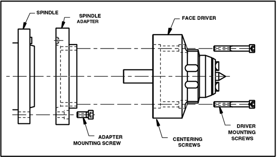
Figure 2. Direct mounting of a face driver using a spindle adapter.
With proper selection, one face driver can be used to run a broad range of parts of various diameters and lengths. The key factor is the diameter of the circle formed by the drive pins, known as the driving, or gripping, diameter (Figure 3). The part diameter should be no more than three times the gripping diameter, and the part length should not exceed 15 times the gripping diameter.
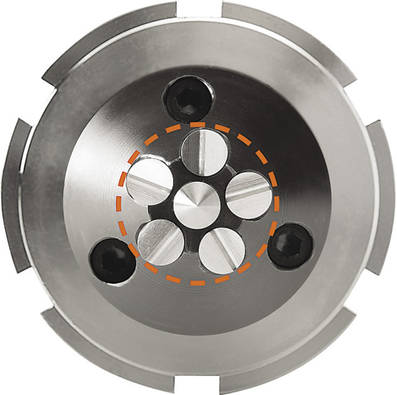
Figure 3. The gripping diameter is the diameter of the circle that touches the outside edges of the drive pins.
To illustrate, let’s assume the drive pins have a gripping diameter of 1″ (25.4mm). Consequently, these pins can turn a part up to 3″ (76.2mm) in diameter and up to 15″ (381mm) in length. To increase system flexibility, each driver comes with three sets of drive pins that grip at different diameters. In our example, this driver would come with drive pins that grip at 1″, 1.2″ (30.5mm) and 1.4″ (35.6mm) in diameter. Each set of drive pins can turn larger and longer parts based on their respective gripping diameters.
Parts can be loaded and clamped in seconds, both manually and automatically. Load and unload times are consistently faster than using drive dogs or chucks. Changing drive pins and center points takes less than a minute. The repetitive nature of the process, with the part held securely between centers, also lends itself to automation. All this adds up to higher throughput, less downtime and more productivity.
Turning to Face Drivers
In turning applications, face drivers can grip a variety of work materials. The most common material types are forgings and bar stock. Brass, aluminum, low-carbon steel and other “soft” metals with hardnesses typically less than 40 HRC are easily turned with a standard face driver. Hard turning can also be accomplished on metals with hardnesses from 40 to 65 HRC, including tool steels and other high-tensile-strength alloys. To ensure sufficient gripping force, carbide-tipped or diamond-plated drive pins are recommended.
Review the print ads from this magazine to continue
This quick advertiser review unlocks the rest of the article and keeps the full-screen reader focused on the ads instead of the page chrome.


MFGAxis Discussion