Balanced equations: Toolholder vibration makes for miserable machining, but balancing can help
Unbalanced tool holders create excessive heat in the spindle bearings, which, along with the vibration, can cause premature spindle failure.
I recently installed a new ceiling fan in the living room—twice. The task had been on my honey-do list for weeks, and by this point it was install the fan or pull weeds. Of course, I ignored my wife’s suggestion to first read the instruction manual. “It’s just a few wires, dear,” I told her. “Nothing to worry about.”
The job done, the ladder stowed safely in the garage, I set the fan to high and flipped the switch. Boy, was I glad to have this one behind me. Then I heard a loud WONK-WONK-WONK … CRASH! The ceiling fan had ripped itself from its mount and cartwheeled into the coffee table. It was only then that I noticed the little packet of balancing weights in the bottom of the fan box.
Courtesy of Haimer USA
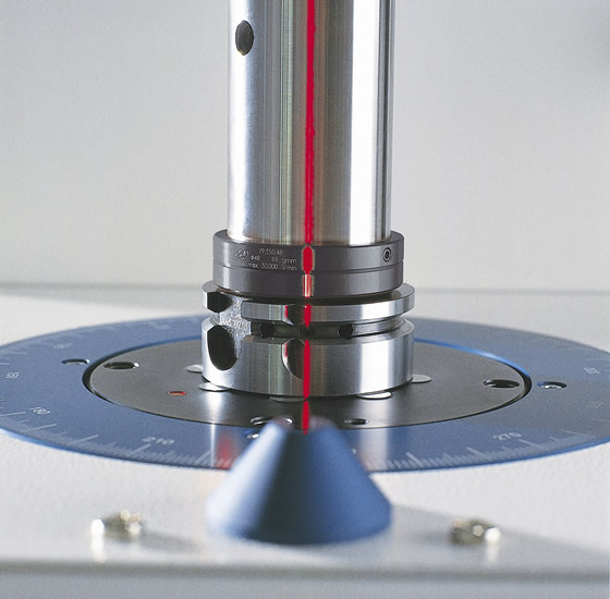
A laser guides the position of balancing rings on a toolholder to displace weight and correct unbalance on a Haimer TD-2009 balancing machine.
With my wife’s helpful advice still ringing in my ears, I drove to the hardware store for another fan kit, reflecting all the while on the importance of balancing. Jet engines, wind turbines, automobile wheels and even ceiling fans—basically any rotating mechanical component—must be balanced. This is certainly true on machining centers.
As proof, load a large commodity toolholder—an unbalanced chunk of steel weighing several pounds or more—into a machine’s spindle and crank it up to 15,000 rpm, if possible. That low hum is the spindle’s cry for help. Michael Minton, national application engineering manager at Methods Machine Tools Inc., Sudbury, Mass., said unbalanced toolholders create excessive heat in the spindle bearings, which, along with the vibration, can cause premature spindle failure. An unbalanced holder’s high degree of runout also reduces cutting performance.
The performance problems can include movement of the toolholder within the spindle taper, leading to premature tool wear and breakage. Chatter and surface finish problems are common, as well as geometric tolerance errors caused by tool runout. The result, Minton said, is that operators, facing reduced cutting performance with unbalanced toolholders, throttle back on feed rates and spindle speeds in an attempt to alleviate a problem over which they have little control. Simply put, out-of-balance toolholders are not only bad for the machine, they also hurt the bottom line.
But when is balancing really needed? Many in the industry feel that only those shops machining at extreme spindle speeds require those fancy and expensive balanceable toolholders and an even more expensive balancing machine to keep them humming. Yet Bob Russo, national sales manager for tooling and accessories at Methods, recommends just 9,000 rpm as the starting point at which balancing becomes important—a relatively ho-hum speed in many shops.
Nuts and Bolts of Balancing
Talk to a balancing expert and you’ll be presented with a series of complex equations, utilizing values such as rotor and unbalance mass, angular velocity and displacement of mass center. The combination of these values ultimately determines a toolholder’s balance quality, or G value. The higher the number, the worse the unbalance at a given speed. Therefore, a G2.5 grade tool spins truer than one balanced at G6.3.
You’ll also hear some esoteric words—couple, static and dynamic—that describe the various ways in which rotating bodies experience imbalance. Get a flat tire while driving down the Interstate and your wheel now suffers from static imbalance (too much weight on one side). Bend the propeller on your fishing boat and you’ll feel dynamic imbalance—excess weight on two or more points—all the way to shore. And too much weight on opposing blades of your ceiling fan results in couple imbalance.
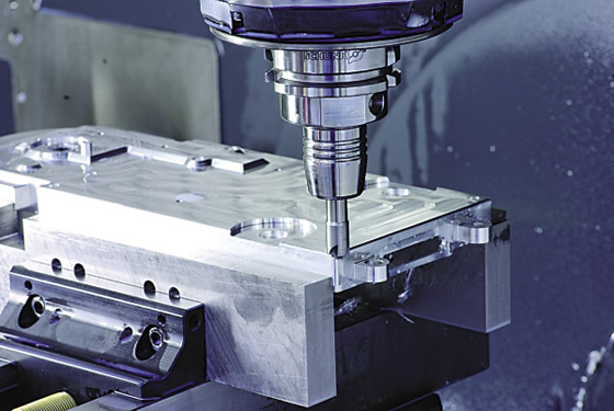
Courtesy of Schunk
A corner-rounding operation on an aluminum workpiece using a balanced Tendo toolholder from Schunk.
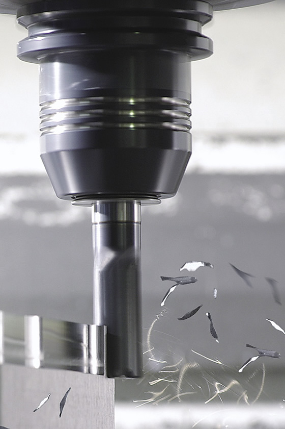
Courtesy of Schunk
High-speed milling aluminum with a Tendo E compact hydraulic workholder from Schunk.
The more weight added or the faster something spins, the greater the imbalance, regardless of a toolholder’s G value. Centrifugal force increases at the square of rotational speed, so as a spindle revs up, vibration increases exponentially.
For example, a toolholder imbalance headache at 3,000 rpm will be 25 times worse at 15,000 rpm. This is why a collet chuck rated at G2.5 might be perfectly fine at 10,000 rpm, but spin that same tooling assembly up to 50,000 rpm and you’ll likely be busy shopping for new machine tool spindle bearings before month’s end.
As previously noted, toolholder imbalance affects more than the machine tool. “Running an unbalanced toolholder is the machining equivalent of trying to write a letter while driving at 60 mph down a bumpy road.” That’s according to Wes Stanulis, engineering manager at toolmaker MAPAL Inc., Port Huron Township, Mich.
The degree to which vibration affects cutting in an unbalanced situation depends largely on the workpiece material. With softer materials, such as aluminum, vibration affects surface finish more than tool life, sort of like dragging a sharp knife across a stick of soft butter during an earthquake. If the butter’s frozen hard as steel, that tasty dairy product will be less susceptible to vibration, but the cutting tool is more likely to chip or wear prematurely.
Balanced Opinions
All metaphors aside, these are murky waters and every toolmaker has his own spin on acceptable levels of toolholder imbalance. Methods’ Russo said the industry standard is G2.5 at 15,000 rpm. For a shop hogging 4130 castings all day at 3,000 rpm, this is clearly overkill, whereas a moldmaker hard milling cavities at 35,000 rpm may find this balance level unacceptable. The level required depends on a number of factors, including part tolerance and surface finish requirements, spindle rpm and quality, feed rates and DOC, the material being machined, and expectations for tool and spindle life.
Throw the enormous variety of toolholders into the equation—anything from CAT and BT to HSK and shrink fit—and an already complex situation becomes truly mind-boggling. For example, the venerable CAT 40 holder is inherently unbalanced due to its uneven drive slots. Weldon-style endmill holders, with their large setscrew on one side, are as well. Stanulis suggested that shops looking for a balanced toolholder would do well to keep things simple. “Choose toolholders where the repeatability of the clamping mechanisms has the least effect on the balanced condition. For example, the repeatability of the HSK shank from a balance perspective is very good when compared to some of the other common tool shanks. The fewer parts you have in your clamping mechanism, the better off you’re going to be. Thermal or shrink-fit toolholders are good choices since they do not have any clamping components.”
A toolmaker that offers factory-balanced holders is Morrisville, N.C.-based Schunk Inc. “We sell a ton of hydraulic holders. They have a seal, piston and screw on one side of the holder, which causes imbalance,” said Tooling Group Manager Matt Panosh. “We have to remove a large amount of material from the opposite side of the holder to offset this. Once this is done, however, the holders repeat very well.”
Still, many in the industry take balance for granted. “Balanced toolholders have become so common that I forget we even do it,” Panosh said. “The only time I ever hear about balance problems anymore is in really high-speed situations, 40,000 rpm and up. That’s because the holders used in this realm are very small and difficult to balance—there’s simply not enough mass in them for the balancing machine to detect any weight difference.”
The balancing machine is a critical part of the toolholder balancing formula for shops and toolmakers alike. Many toolmakers deliver their toolholders prebalanced, which in Schunk’s case means the holders are machine-balanced to G2.5 at 25,000 rpm. Once that toolholder hits the shop floor, however, all bets are off—mount a different tool in that holder and the assembly as a whole could end up more unbalanced than my 2-year old grandson on a skateboard.
Panosh agreed that a balanced assembly is important, but offered this caveat: “It depends on the kinds of tools you’re running and what you’re doing with them. The industry is inundated with 20 “×40 ” vertical milling machines, most of which max out at 12,000 rpm or so. At these speeds, balancing the assembly isn’t always necessary, as long as you’re using high-quality balanced toolholders and cutting tools.”
Tricky Stuff
Someone who might take exception to this is Brendt Holden, president of tooling provider Haimer USA LLC, Villa Park, Ill. “With mechanical holders such as milling or collet chucks, the assembly should be balanced every time you change the cutting tool,” Holden said. “That’s because these types of holders contain moving components that don’t repeat exactly during clamping. Even hydraulic chucks are susceptible to imbalance as the fluid level changes during clamping.”
Review the print ads from this magazine to continue
This quick advertiser review unlocks the rest of the article and keeps the full-screen reader focused on the ads instead of the page chrome.


MFGAxis Discussion