



Setting up for single-piece flow
The Shop Technology column in the July 2013 issue of Cutting Tool Engineering magazine continues to explore one shop's move from batch processing of machining jobs to a single-piece flow.
To recap my last two columns, Savannah Machinery Works is moving from batch processing of machining jobs to single-piece flow to improve lead times, reduce the risk of propagating defects and add flexibility to machine tool scheduling.
Single-piece flow in a low-volume environment can create long setup times. Therefore, careful planning and consideration of the fixture/machine tool interface is critical to establishing efficient setups. Without efficient setups, the benefits of single-piece flow are not maximized.
As I described last month, we are configuring our machine tools and fixtures to have a common interface, allowing us to shorten setup times from hours to minutes. By using tombstones and subplates with a common bolt and locating pin pattern, we can locate fixtures accurately enough so no adjustment is required. This enables an operator to place the fixtures in the correct location each time.
In addition, we are utilizing technology to reduce setup times. For example, when we first set up the shop, each machine tool was purchased with a part probe and a tool probe for setting length. The probes are critical for implementing single-piece flow. Our wireless part probes are carried in the tool magazine. The table-mounted trigger tool probes are capable of measuring only length, but I hope to eventually upgrade to laser setters that also measure tool diameter.
Using the marked columns and rows on the subplates and tombstones, an operator places the fixture on the machine table in a predetermined location. After clamping the fixture and part, the operator selects the appropriate program and starts the machining cycle. He then unloads the completed part and starts the next scheduled part.
Each fixture has a datum feature, such as a bored hole or tooling ball, that corresponds with the coordinate system in the CAM software; programs begin from this common origin. The part probe then verifies the fixture location by probing a known location, and comparison of the datum location to the programmed value tells us if the fixture has been correctly located. By using logic statements in the code, we poll the machines to compare the measured locations to the predetermined locations and command the machine to stop and display a message if an error is found.
All images courtesy of C. Tate
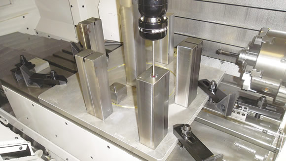
A part probe is ready to verify the fixture location and set the work offsets on an Okuma vertical machining center at Savannah Machinery Works.
We can probe the part to verify it has been properly loaded using the same method, again forcing the machine to stop and display a message if a large error is found. If the part is correctly located, the probe will fine-tune the coordinate system for the part before the program continues.
We must measure cutting tools using the tool probe after setting the coordinate system. Our controls have canned cycles that can be initiated from the body of a program, and each tool used in the program is measured. We do this to verify length data is correct, tools are not worn beyond desired limits and there are no broken tools. Again, if a large error is found, the machine is commanded to stop and an alarm is displayed.
After verifying the condition of the tools, the part is machined. Part probing occurs again after machining to measure critical part dimensions. During initial implementation of the single-piece flow strategy, we will simply command a machine to stop and display an error if a part is out of tolerance. A manufacturing engineer and operator will handle needed corrections.
We will modify programs to include logic statements that automatically correct tool data discrepancies based on measurements after successfully implementing the strategy. We will only go to this level of complexity if we see frequent errors in the measurements of critical dimensions. We also plan to generate data collection and analysis reports that can be used to measure the capability of a machining process.
If we use a machine to verify part dimensions, part probe calibration must be maintained so the machine does most of the work. Calibration is accomplished by keeping an artifact, which is certified and traceable to NIST standards via a calibration lab, on the machine table.
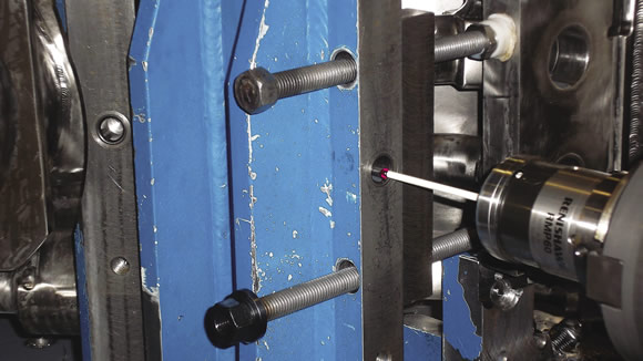
Probing takes place on a 1,350mm horizontal boring mill, which Savannah Machinery Works uses to machine large weldments that measure 1,000mm tall and weigh 300 lbs.
The artifact should reside in a known position and have documented dimensions. Calibration compares the known dimensions to the measured dimensions. If the measured values are acceptable, the probe measures the part. If the measured values exceed the allowable limits, the machine stops and provides an error code.
Our goal in implementing single-piece flow is not to eliminate skilled operators, but to maximize their opportunities to add value to finished parts. When skilled employees are setting tools, aligning fixtures and inspecting parts, they are not adding value. Automating the necessary non-value-added setup tasks means operators have more time to perform tasks that do add value, such as machining parts.
This level of automation also reduces the total cycle time required to produce a part while enabling an operator to run multiple machines. Single-piece flow would not be possible if operators were required to perform non-value-added setup tasks. CTE
 About the Author: Christopher Tate is manufacturing engineering lead for machining at Mitsubishi Power Systems, Savannah (Ga.) Machinery Works, a global builder of gas and steam turbines. He has 19 years of experience in the metalworking industry and holds a Master of Science and Bachelor of Science from Mississippi State University. E-mail: chris23state@gmail.com.
Glossary terms in this article
Related




Subscribers can use MFGAxis notes, saves and discussion tools with their innoNET account.


