

Transmitting tool
The Look Ahead department in the April 2013 issue of Cutting Tool Engineering also looks at a mechatronic cutting tool for large back counterboring and back spotfacing applications.
Safely and efficiently back spotfacing and back counterboring large holes for applications such as gas and steam turbines and wind turbine gearboxes can be a challenge. This is because the workpiece weight often prevents the part from being optimally rotated, or positioned, for a machining operation that faces away from the spindle side of the bore. In addition, the machine may not have enough axes to apply a conventional tool, such as a milling tool, according to Bernd Aschenbach, a scientist at GFE – Gesellschaft für Fertigungstechnik und Entwicklung Schmalkalden e.V. (Society of Production Technology and Development).
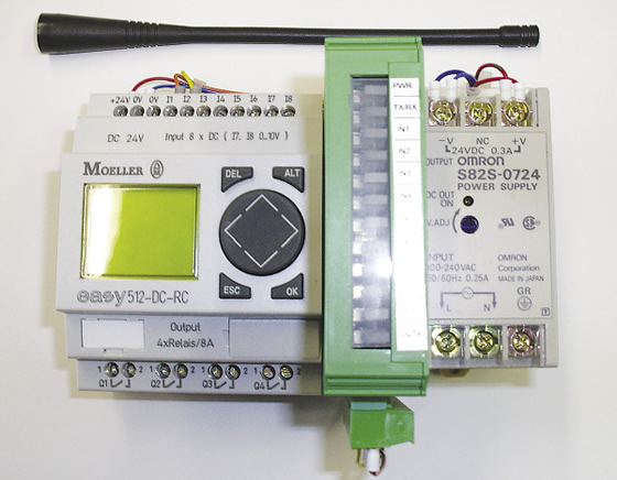
Courtesy of GFE
The stationary interface, or base station, for GFE’s mechatronic tool can be located in a machine’s control cabinet.
Therefore, GFE developed a prototype mechatronic cutting tool for these applications, which uses bidirectional telemetry to gather information about tool status during cutting. (Mechatronics incorporates mechanical and electronics engineering concepts.) “The use of mechatronic tools with integrated sensor-monitored actuators can help reduce the amount of work required when back counterboring and back spotfacing on large machining centers while retaining high levels of process dependability,” Aschenbach said.
Depending on the application, he noted a mechatronic tool can use magnetic Hall and eddy current sensors, optical sensors such as cameras and lasers, and other sensors to monitor and influence the machining process, but they have no direct influence on the tool. For example, two Hall sensor integrated circuits can monitor the end positions of a hydraulic cutting drive, or piston, which tilts the cutting edges. Coolant actuates the piston, causing the insert holders to pivot outward, and the tool can be guided axially back through the pilot bore after the coolant is turned off, causing the insert holders to pivot inward.
Review the print ads from this magazine to continue
This quick advertiser review unlocks the rest of the article and keeps the full-screen reader focused on the ads instead of the page chrome.
Advertisers included in this article experience
Print placements connected to this article
Kyocera’s M-Series
The latest members of
Milling Cutter Arsenal The M-Four and M-Six Milling Cutters featuring double-sided, thick edge inserts and long lasting MEGACOAT NANO Grades for superior performance t ough pre c ise unchallenged Experience the M-Series Difference The M-Four and M-Six Milling Cutters are now available as part of the Kyocera Milling Kit Sale
The latest members of Kyocera’s M-Series Milling Cutter Arsenal The M-Four and M-Six Milling Cutters featuring double-sided, thick edge inserts and long lasting MEGACOAT NANO Grades for superior performance
Visit Kyocera’s M-Series View this placement in the issue recordPrint ads from this magazine
Milling Cutter Arsenal The M-Four and M-Six Milling Cutters featuring double-sided, thick edge inserts and long lasting MEGACOAT NANO Grades for superior performance t ough pre c ise unchallenged Experience the M-Series Difference The M-Four and M-Six Milling Cutters are now available as part of the Kyocera Milling Kit Sale
The latest members of Kyocera’s M-Series Milling Cutter Arsenal The M-Four and M-Six Milling Cutters featuring double-sided, thick edge inserts and long lasting MEGACOAT NANO Grades for superior performance
Continue reading
April 2013
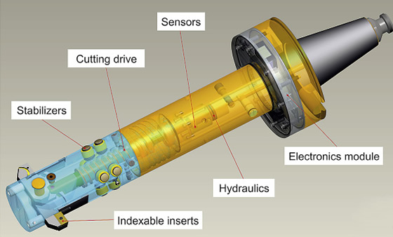
Courtesy of GFE
A 3-D model of the prototype mechatronic cutting tool for back spotfacing and back counterboring.
The data is transmitted to the stationary interface, or base station, at a frequency of 430MHz, and signals from the interface can control the machine, such as stopping the machine when a malfunction occurs. “Our prototype transmits the angular positions of the cutting inserts,” Aschenbach said, adding that the interface can be located in a machine’s control cabinet.
With systematic testing, he added that GFE plans to explore commercial feasibility of the prototype tool.
For more information, contact GFE, Schmalkalden, Germany, at 011-49-36-83-69-00-0 or www.gfe-net.de. CTE
Glossary terms in this article
Related




Subscribers can use MFGAxis notes, saves and discussion tools with their innoNET account.


