

Concentric engineering: Turning Performance
In addition to handling prototype and production machining, R.E.F. Precision Products LLC, Deer Park, N.Y., provides engineering and productivity consulting services.
In addition to handling prototype and production machining, R.E.F. Precision Products LLC, Deer Park, N.Y., provides engineering and productivity consulting services. “You give me what you are looking for, and I’ll engineer it to make it as cost competitive as possible,” said Co-owner Rob Fleece, whose background is in mechanical engineering. In some cases, R.E.F. Precision’s engineering expertise not only helps controls costs, but enables the shop to make difficult-to-machine parts.
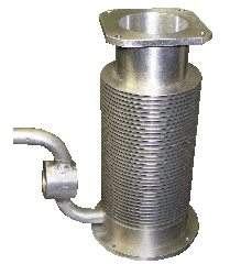
When R.E.F. Precision Products manufactured this 8 “-long, 35⁄8 “-dia., 6061 aluminum heat sink for a computer-chip-making machine, it consolidated critical machining steps on one CNC lathe to assure concentricity of the part’s ID and OD. Image courtesy of R.E.F. Precision.
One example was an 8 “-long, 3⅝ “-dia., 6061 aluminum heat sink for a machine that makes computer chips. To permit rapid heat transfer, the part has 36 delicate cooling fins and interior walls as thin as 0.020 “. Because of the thin walls, concentricity between the part’s ID and OD was crucial. “If you don’t have dead concentricity, sometimes you’ll get a leak and a bad part,” Fleece said.
R.E.F. Precision’s customer attempted to make prototypes of the heat sink, but six out of 10 failed leak testing at 1,200 psi. According to Fleece, the problem was in the customer’s machining process, in which chucking and rechucking the part diminished its ability to maintain concentricity.
As a result, Fleece devised a process that produced all critical dimensions in one chucking. He began with 3.75 “-dia., 1 “-thick-wall tubing. The tubing was cut 1 ” longer than the finished part, so “I had something to hold onto,” he said. He clamped one end of the tubing in a chuck on a Hitachi Seiki CNC lathe and faced the other end with a Sandvik Coromant grade-1025, CNMGP 431 coated carbide insert.
Then he bored the ID to a 0.001 “/ -0.000 ” tolerance with a Kennametal grade-KC5010, coated carbide insert held in a 1 “-dia., solid-carbide boring bar. Because the bore went to the back of the part and thereby might amplify tool vibration, Fleece ran the tool at a relatively low 750 rpm and took three passes, with the first two at a 0.012-ipr feed rate. The feed had to be heavy enough, he said, to produce enough force to minimize chatter. The last pass, at a 0.020 ” DOC, produced a 0.001 “-undersize bore. The boring tool ran at 0.006 ipr. The lighter feed was acceptable for the last pass, “because I was going to hone it to final size and I wasn’t as concerned about the finish,” Fleece said. The bore’s final ID is 1.912 “.
Once boring was completed, Fleece inserted a 0.001 “-undersize plug into the bore and pushed it against the chuck with an arbor on a center clamped in the machine’s tailstock. That enhanced rigidity for subsequent operations. “It almost became like a solid piece again,” Fleece said.
Next, the CNMGP insert roughed and finished the part’s OD to 3.380 “, up to a shoulder at the part’s chuck end. “With the positive-rake insert, I was able to get a really nice finish,” Fleece said. Then he cut a 2.030 “-dia., 1.312 “-wide groove at the front of the part with an ¼ “-wide Allied Machine deep-grooving tool.
Review the print ads from this magazine to continue
This quick advertiser review unlocks the rest of the article and keeps the full-screen reader focused on the ads instead of the page chrome.
Advertisers included in this article experience
Print placements connected to this article
Sumicarbide
Sumitomo’s new AC820P
Sumitomo’s new AC820P Contact Sumicarbide at 800-950-5202, email [email protected], or visit sumicarbide.com.
Visit Sumicarbide View this placement in the issue recordPrint ads from this magazine
Sumitomo’s new AC820P Contact Sumicarbide at 800-950-5202, email [email protected], or visit sumicarbide.com.
Continue reading
August 2009
Each cooling fin is 0.030 ” thick and separated by 0.100 “-wide × 0.460 “-deep grooves. Fleece tried a number of tooling alternatives to create the fins and found his Seco cutoff tool worked best. He custom ground both sides of a 0.120 “-wide cutoff insert to produce a 0.100 “-wide tool.
He plunged the tool straight in at 400 sfm and 0.005 ipr to a depth of 0.200 ” for all 36 fins, returned for another 0.200 “-deep pass for every one and finished each fin with a 0.060 “-DOC final pass. When trying to cut a fin in a single pass, Fleece said the 0.030 “-thick walls started to push away, so he machined them in steps. Initially, Fleece reground the insert once or twice to get the proper clearance, and “once we got the insert perfect it just worked.” R.E.F. ran 100-part batches, and one cutoff insert typically would last for an entire run.
After the fins were completed, Fleece backed off the machine’s center, removed the plug and applied the grooving tool to cut off the part. For that operation, he ran the tool at the same 0.006-ipr feed rate but at a 150-sfm cutting speed to minimize vibration and impart a fine surface finish.
Fleece said when the part came off the lathe, “Everything was concentric and perpendicular, because it was all made at once.” Manual finishing included minimal deburring and treatment with Scotch-Brite pads to clean the fins.
The part was then moved to a Bridgeport 760 vertical machining center, where it was clamped on an expanding arbor. Four 0.212 “-dia. holes, later to be fitted with press-in clinching screws, were drilled in the flange on the front of the part. Then the flange edges were squared with an endmill. Finally, the part was flipped, clamped again on the arbor and four clearance holes were drilled to accept 0.440 “-dia. screws. Milling and turning consumed 22 minutes.
The finished heat sink has an S-shaped connecting tube welded near its base. R.E.F. Precision turned a simple bushing-shaped part to be welded in the middle of the “S” between two pieces of tubing. R.E.F. Precision also engineered a fixture that positioned the tubing parts, bushing and heat sink for welding, which was outsourced. CTE
For more information about R.E.F. Precision Products LLC, call (631) 242-4471 or visit www.refprecisionproducts.com.
Glossary terms in this article
Related




Subscribers can use MFGAxis notes, saves and discussion tools with their innoNET account.


