

Cylindrical die thread rolling is quick and economical
The process is suitable for making a variety of everyday products, achieving fast, economical production when metalcutting machining just doesn't cut it.
Cylindrical die thread rolling is a cool method for taking the heat off manufacturing thin, deep helical fins on long lengths of thin-walled tubing. The process is suitable for making a variety of everyday products, achieving fast, economical production when metalcutting machining just doesn’t cut it. One such product is finned tubing for heat exchangers.
Improving the energy transfer efficiency of cooling and heating fluids has been a challenge since the Industrial Revolution. Any device performing work requires a transfer of energy to make the work happen. A portion of the energy goes into the work, and another portion comes out as heat due to efficiency losses in the system. Methods that improve the energy transfer efficiency of the original device or that capture the heat loss for reuse are in constant demand. It all comes down to heat transfer.
Heat transfer can be accomplished by a heat exchanger, which transfers energy from one fluid to another liquid or a gas. One of the simplest methods of heat exchange without mixing fluids is the use of a tube through which one fluid is passed at one temperature while another fluid is passed around the outside at another temperature. Heat is transferred from the hotter fluid to the cooler one through the tube wall. To increase heat exchange efficiency, such a tube is manufactured with fins that protrude radially outward from the tube surface, thus creating a fin tube. Finned tubing can be found at the core of most heat exchanger devices.
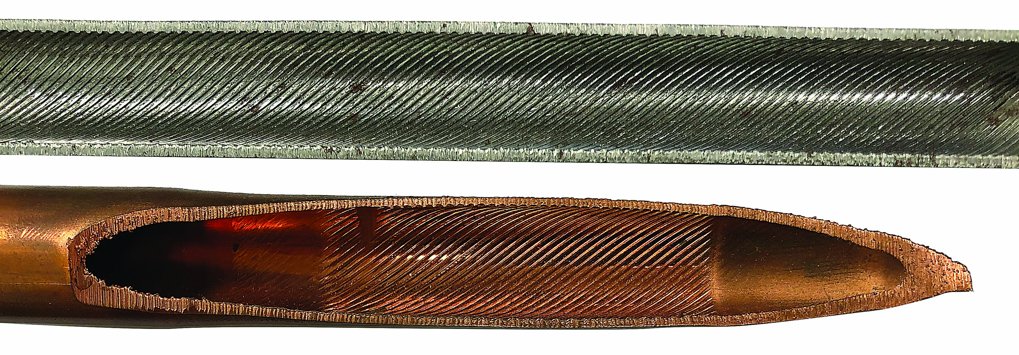
A fin tube cross section with internal profiling. Image courtesy of Kinefac
Why a Fin Tube?
The simple answer is that the efficiency or rate of heat transfer is affected significantly by the surface area of exposure. Fluids have a heat transfer coefficient, which is the amount of heat per unit area they can transfer. By increasing the usable area, multiplying the heat transfer coefficient by that increased area results in more capacity for heat transfer. The outside surface area of a plain tube easily can be increased five to 20 times by adding fins to the outside surface.
A fin tube also can have a finlike profile on the inside surface to increase the surface area and promote directional fluid flow or mixing. Turbulence induces mixing of each fluid, which can improve heat transfer for individual fluids. Turbulence can be controlled by the geometry and arrangement of the fins on the inside or outside of the tube. A helical fin path is most common on either or both surfaces.
Before talking about manufacturing finned tubing, let’s look at the characteristics of a typical fin tube product. Fin tubes come in all shapes, sizes and materials with varied fin heights and thicknesses. The tubes generally are made of welded tubing in stainless and low-carbon steels, copper, brass, aluminum and exotic alloys. One important characteristic to consider for manufacturing is length. Some fin tubes are manufactured in continuous lengths of 100′ or more, which then are bent into compact shapes to fit inside various heat exchangers. Other relevant traits are tube diameter and wall thickness, fin height, the number of fins per inch and tube material grade and construction.
In simple terms, a fin tube can be thought of as a hollow, threaded rod. However, the simplicity starts to diminish when there are 60 or more thin threads per inch with an additional threaded profile on the ID over a 100′ length. Two processes traditionally are employed to produce external threads on the outside of a workpiece: thread cutting and thread rolling. Both methods have strengths and weaknesses. Thread rolling is the process to beat, though, when it comes to manufacturing fin tubes at high rates of speed. There are also benefits with material savings, strength, surface quality and the ability to generate internal profiles without wasting material by generating chips.
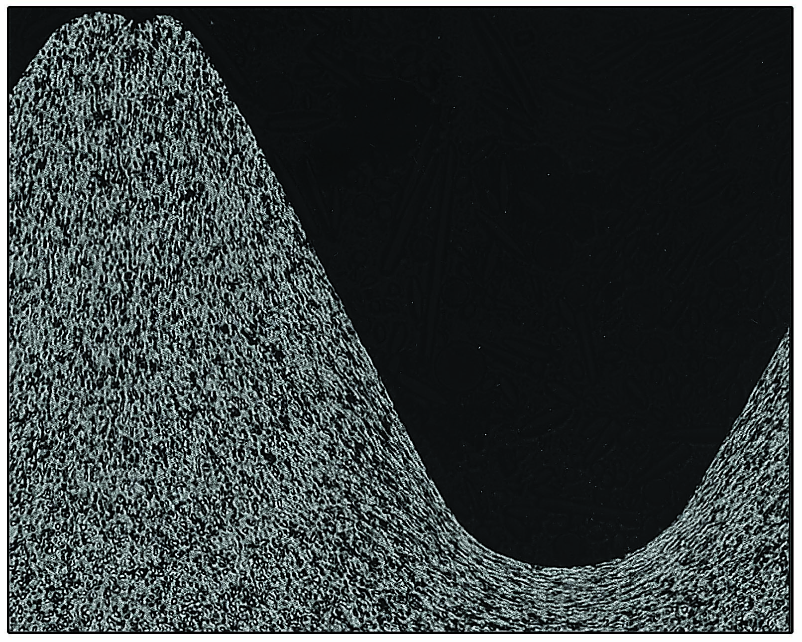
A cross section of rolled thread grain flow. Image courtesy of Kinefac
When cutting an external thread on a lathe, a single-point cutting tool plunges radially into one side of the workpiece and traverses along its exposed length. Multiple passes at successively deeper depths usually are required to achieve the full thread form. It can take minutes to accomplish this task on a length less than 10″ or 12″. Single-point thread cutting creates a force imbalance on one side of the workpiece due to the forces generated by the cutting tool.
Deflection of the workpiece is always a consideration. The workpiece geometry and cutting forces dictate the limits of exposed length that can be threaded, above which deflection and stability problems will occur. Once the limit is exceeded, rolling is the best option.
Rolling Basics
When rolling an external thread of discrete length, two or three rotating cylindrical dies plunge radially into the workpiece to some depth while rotating it to replicate their geometric surface features into the periphery of the workpiece surface. This is referred to as infeed rolling. For longer continuous lengths of a threaded product, the through-feed rolling process is used by skewing the axes of the rolling dies at an angle to generate through-feeding action of the workpiece.
In either case, the blank material is forced to conform to the die geometry without removing or gaining material. Therefore, thread rolling is a constant-volume process. The starting pre-roll blank is smaller in diameter than the final thread major diameter—usually somewhere near the thread pitch diameter—because material from the blank is displaced radially outward by the dies to fill the form. Material also can and will flow in two other principal directions, axial and circumferential, depending on several factors, such as the degree of form fullness or the ratio of thread depth to root diameter.
A typical machine screw thread can be rolled into a bolt blank in a few seconds. The feeding of the bolt blank into and out of the rolling machine usually takes longer than the rolling process itself. Rolling generates an uninterrupted grain flow around the rolled root, which helps enhance strength to a rolled thread over a cut thread. Other characteristics, such as material workhardening and a highly burnished surface from the rolling action, also help increase the strength and quality of a rolled thread.
Review the print ads from this magazine to continue
This quick advertiser review unlocks the rest of the article and keeps the full-screen reader focused on the ads instead of the page chrome.
Advertisers included in this article experience
Print placements connected to this article
Archcuttingtools.Com
BRINGING A NEW SYNERGY
TO CUTTING TOOL SOLUTIONS T-SLOT Cutter HSS Corner Rounding endmill Standard Cutter-Side Mill by • Milling Cutter-HSS, Cobalt, Carbide and Carbide Tipped, with a wide range of Coating Options • 6,000 unique standard tools including: - HSS and Cobalt Saws - Corner Rounding Endmills HSS and Cobalt, in English and Metric sizes
ARCHCUTTINGTOOLS.COM BRINGING A NEW SYNERGY TO CUTTING TOOL SOLUTIONS T-SLOT Cutter HSS Corner Rounding endmill Standard Cutter-Side Mill by • Milling Cutter-HSS, Cobalt, Carbide and Carbide Tipped, with a wide range of Coating Options
Visit Archcuttingtools.Com View this placement in the issue recordPrint ads from this magazine
TO CUTTING TOOL SOLUTIONS T-SLOT Cutter HSS Corner Rounding endmill Standard Cutter-Side Mill by • Milling Cutter-HSS, Cobalt, Carbide and Carbide Tipped, with a wide range of Coating Options • 6,000 unique standard tools including: - HSS and Cobalt Saws - Corner Rounding Endmills HSS and Cobalt, in English and Metric sizes
ARCHCUTTINGTOOLS.COM BRINGING A NEW SYNERGY TO CUTTING TOOL SOLUTIONS T-SLOT Cutter HSS Corner Rounding endmill Standard Cutter-Side Mill by • Milling Cutter-HSS, Cobalt, Carbide and Carbide Tipped, with a wide range of Coating Options
Continue reading
August 2019
The aforementioned advantages make the rolling process suitable for mass production of a long, continuous fin tube product that has good strength characteristics and process stability. Hollow components have relatively thin walls, which require a form to be rolled on them, and are processed using three-cylindrical die rolling. The three dies simultaneously converge on the workpiece, trapping it on a constant centerline while substantially preventing deformation of the tube with balanced forces at each die contact. An internal supporting mandrel sometimes is positioned inside the tube under the deformation zone to provide additional stability.
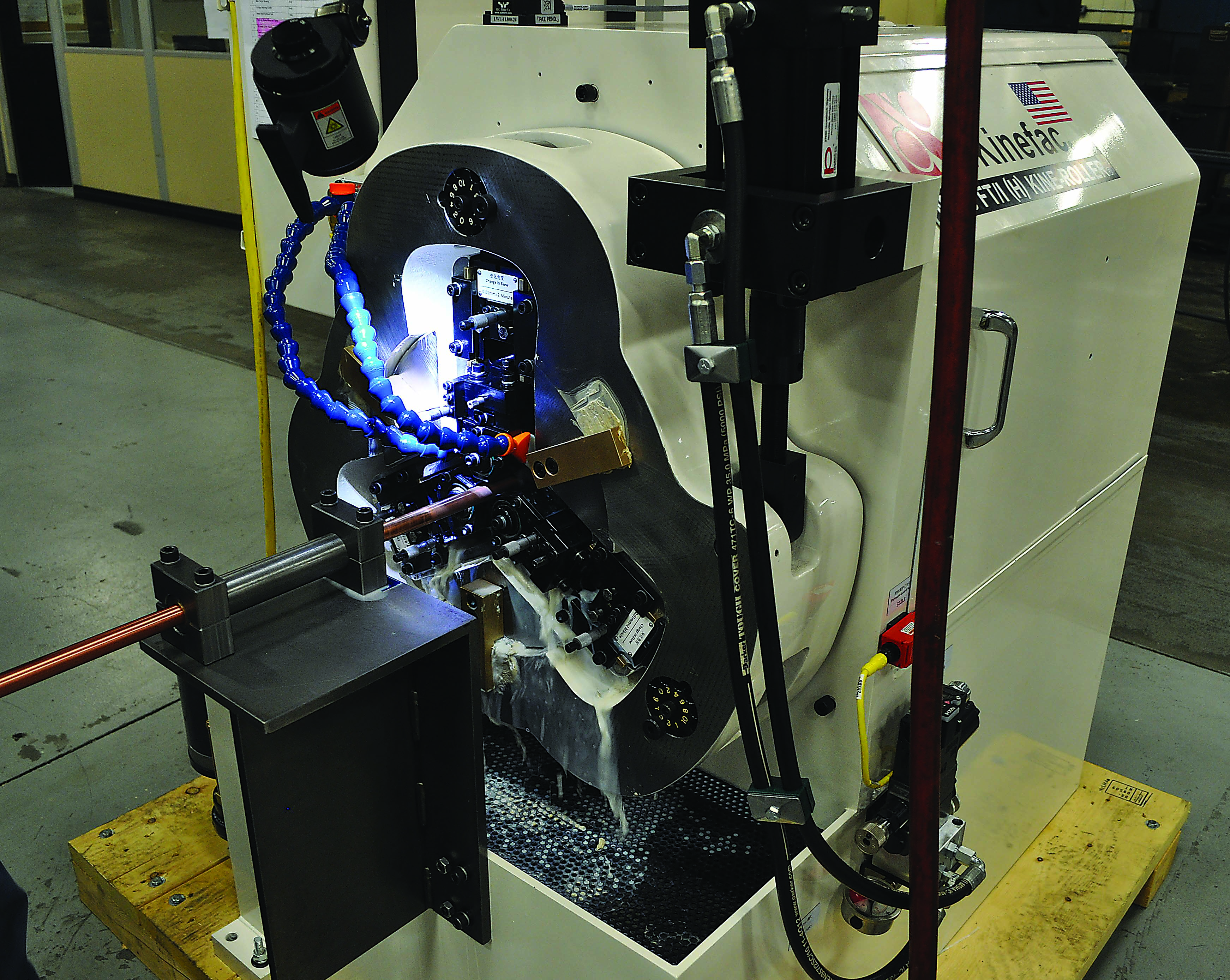
Kinefac’s MC-6 FT/I high-precision fin tube rolling machine. Image courtesy of Kinefac
As an added benefit of the rolling process, the internal mandrel can be made with a helical profile on its surface to replicate a helical form on the inside diameter of the tube, the benefits of which were described earlier. This operation would be impossible for long lengths of tubing using a cutting tool on the end of a boring bar.
Compared with cutting, the three-die through-feed rolling process can roll continuous lengths of form at high speed. Thin-wall rolling applications are also more susceptible to increased axial material flow. With fin tube rolling, depending on the depth of form and change in the cross section area in the rolling deformation zone, there can be significant axial stretching of the tubing on the order of 10% to 20%. That is 10% to 20% less blank tubing length required as raw material input.
Speed and Flexibility
It is not uncommon for fin tubes with low fin heights and 15 to 20 fins per inch to be rolled in upward of 10′ or more per minute using straight annular disc dies. That’s 2 in./sec. of a finish-rolled product. Production rates depend on the number of fins per inch, the number of helical start paths on the tube, die speed, die skew angle, tube diameter and die diameter. When using straight annular discs, the disc die skew angle is matched to the part lead angle. As the number of helical start paths on the tube increases, the die skew angle must increase to match the higher lead angle. A higher skew angle means faster feed rates at a given disc rpm.
As previously noted, long lengths of fin tubes typically are bent into special shapes to fit inside a heat exchanger shell. It is desirable to have no fins present where bends occur when performing a bending operation. This avoids fin damage and takes advantage of the full tube cross section. Fin rolling machines can provide radial motion of the disc dies both into and out of the tube to allow spacing between finned sections as required. The tube advances axially through the dies during the period of die retraction to create a length of space before plunging the dies back into the tube to continue producing rolled fin.
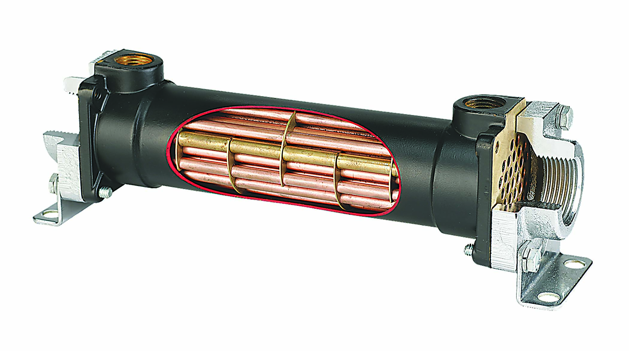
A typical shell and tube heat exchanger. Image courtesy of Thermal Transfer Systems Inc.
It is critical that all the fin rolling dies simultaneously contact the workpiece to maintain a constant rolling centerline and full stability during rolling. It is also critical to sustain constant radial position of the penetrated dies into the tube throughout the rolling process to maintain dimensional stability of the rolled tube root diameter and fin height.
For shops with high-volume production or that struggle to cut continuous lengths of finned tubing or other helical and annular threadlike forms, consider cylindrical die through-feed rolling. Production speed, material savings, strength, quality and performance can justify the capital expense.
For more information about thread rolling, view a video presentation at www.ctemag.com by scanning the QR code on your smartphone or entering this URL on your web browser: cteplus.delivr.com/24y3t
A Brief History of Thread Rolling
Roll forming has existed since ancient times and can be traced back to when potters pressed and rolled a piece of clay between their hands to roll it into a new size. The first partially mechanized, hand-operated roll-forming devices for working metal appeared in the 1600s and pressed ridges into the sides of coins to deter thieves from scraping away shavings of the precious metals.
In the mid-1800s, the first fully mechanized flat die and cylindrical die thread-rolling machines were developed for rolling low-precision wood screw threads and higher-precision machined metal screw threads. Demand for higher-quality machined screw threads in the aircraft and automotive industries around the time of World War II pushed rolling machine builders to achieve a new level of quality for mass production of high-precision screw threads.
Today, the rolling process often is used as a secondary or final manufacturing operation to produce high-precision threads and other helical and annular forms in exotic alloys on critical components, such as aircraft landing gear.
—David C. Willens
Glossary terms in this article
QR codes and videos from this issue
Print QR codes, video callouts, and in-magazine links for this article now point to the CTE video hub in the HTML version.







