

Elements for successful endmilling
When an endmill efficiently makes chips, everybody is happy: the end user, the parts buyer, and the cutting tool manufacturer and distributor. Achieving that by having the tool follow the correct toolpaths and run at productivity-boosting parameters, however, requires an endmill with optimized geometry, substrate and coating.
When an endmill efficiently makes chips, everybody is happy: the end user, the parts buyer, and the cutting tool manufacturer and distributor. Achieving that by having the tool follow the correct toolpaths and run at productivity-boosting parameters, however, requires an endmill with optimized geometry, substrate and coating.
“It’s all about optimizing,” said Sherry DePerno, president and CEO of Advanced Tool Inc., Marcy, N.Y., which exclusively produces solid-carbide endmills. And once the pieces of the endmill puzzle are optimized for an application, she emphasized the need for consistency when making the tools. “Operators should be able to put a new tool in and get the same number of parts every time. Inconsistency is not acceptable”
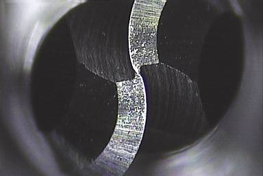
This 2-flute ballnose endmill from Advanced Tool is made with the proper web thickness and gash, which refers to the center of the endmill. A slight “S” curve to the gash, known as a helical gash, runs from the top to the bottom. A helical gash on a ball endmill is an advanced geometry design, enabling less of the cutting edge to contact the part at one time and reducing pressure to the cutting edge.
Gary Schmidt, application engineer for M.A. Ford Manufacturing Co. Inc., Davenport, Iowa, agreed it’s essential to examine all aspects of a customer’s application when providing an ideal solid-carbide endmill rather than merely an acceptable one. “By envisioning the end result, you can apply the right tool.”
One key aspect is the workpiece material. Schmidt recalled an aerospace company that struggled to machine an uncommon, difficult-to-cut material. M.A. Ford did a side-by-side comparison of the customer’s material with a similar material that was able to be effectively cut with a known tool geometry. “We ended up recommending a standard high-performance endmill with a slight modification,” he said. “Side-by-side comparison of work materials is a powerful tool.”
When developing a solution, Advanced Tool incorporates its trademarked Wear Analysis process, which includes microscopic inspection to examine how an endmill is wearing and finite element analysis to help determine which avenues to follow. Based on the analysis, the toolmaker will determine whether to target the substrate, geometry or coating first. “We try to only change one or two elements at a time and build upon that,” DePerno said. “Then we put that tool out in the field, do another Wear Analysis and ask ‘Are we getting further or closer to where we’re trying to be?’ “
For example, when poor tool life occurs, Advanced Tool looks at geometry as a possible culprit, DePerno noted. The endmill may require an adjustment to the core thickness, clearance angles, rake angle or helix angle to improve performance. Poor tool manufacturing can also cause issues. A web that is too thick, for instance, creates a dead area on top of the tool that requires more pressure for it to cut, causing premature wear.
However, end users may not understand a tool’s nuances, which can lead to inefficient cutting and, ultimately, poor tool life. “They want to put an endmill in a holder and cut,” DePerno said. “At the end of the day, it’s all about results.”
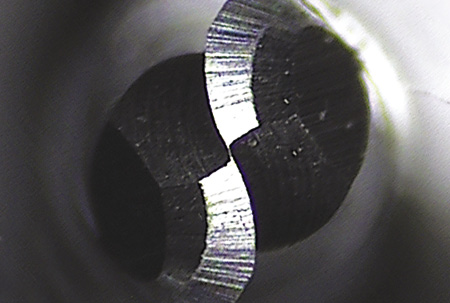
The web shown at the center of this “brand X” 2-flute ballnose endmill is paper thin. It is far too thin for the tool to perform properly, because the section is too weak and will ultimately break during use. This endmill also has a poor surface finish, indicated by the highly visible small lines running horizontally on the cutting edge.
To achieve the desired results, the substrate must suit the workpiece material. “One thing that has not been widely publicized is that aluminum has a tendency to stick to the cobalt in carbide,” said M.A. Ford’s Schmidt. “Carbide substrates that have 6 percent cobalt or less are ideal for aluminum applications.”
Review the print ads from this magazine to continue
This quick advertiser review unlocks the rest of the article and keeps the full-screen reader focused on the ads instead of the page chrome.
Advertisers included in this article experience
Print placements connected to this article
Toolflo
Can be used with low pressure
or high pressure coolant (rated up to 1500 psi) • Available for #2, 3 & 4 Flo-Lock right and left hand inserts • Fits other brand’s standard holders •Available in 6 and 12 pack quantities for an added cost savings! Use Your Existing Holders! Simply replace the top clamp on your standard holder. Contact your nearest Tool-Flo distributor or contact us at:.
Can be used with low pressure or high pressure coolant (rated up to 1500 psi) • Available for #2, 3 & 4 Flo-Lock right and left hand inserts • Fits other brand’s standard holders •Available in 6 and 12 pack quantities for an added cost savings!
Visit Toolflo View this placement in the issue recordPrint ads from this magazine
or high pressure coolant (rated up to 1500 psi) • Available for #2, 3 & 4 Flo-Lock right and left hand inserts • Fits other brand’s standard holders •Available in 6 and 12 pack quantities for an added cost savings! Use Your Existing Holders! Simply replace the top clamp on your standard holder. Contact your nearest Tool-Flo distributor or contact us at:.
Can be used with low pressure or high pressure coolant (rated up to 1500 psi) • Available for #2, 3 & 4 Flo-Lock right and left hand inserts • Fits other brand’s standard holders •Available in 6 and 12 pack quantities for an added cost savings!
Continue reading
February 2015
The lower cobalt percentage also enhances carbide’s hardness, enabling endmills with only up to 6 percent cobalt to tackle abrasive materials, he added. But for an application that requires a tool with more transverse rupture strength, a carbide substrate with 12 percent cobalt is a better choice. The cobalt in carbide acts as a binder for the tungsten particles. Because cobalt is softer than carbide, reducing the cobalt percentage will result in a harder carbide tool, whereas increasing the cobalt percentage will produce a tool that is not as hard but has higher transverse rupture strength and more toughness.
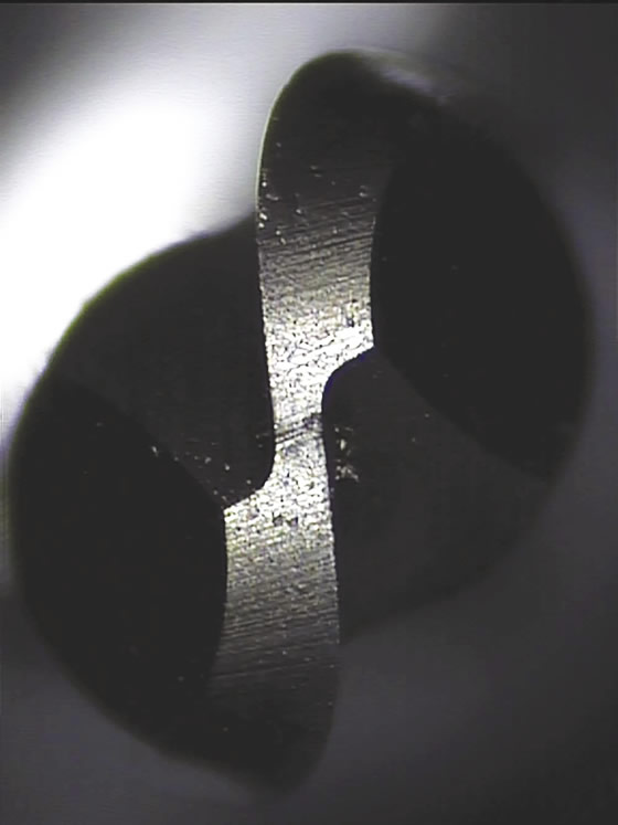
The web on this “brand Y” 2-flute ballnose endmill is too thick, or fat. This means there is a large dead area that won’t cut, exerting more pressure on the endmill. The result is premature failure and/or breakage. In addition, this tool has a straight gash, because there is less of an “S” curve to the gash than a helical gash. A straight gash will need to work harder during use and dull faster.
While all the geometries need to function collectively to optimize the endmilling system, in a nutshell, it comes down to the cutting edge, according to Schmidt. Nonetheless, trade-offs occur when designing tools. For instance, a high rake angle easily shears material and minimizes deflection, but doesn’t always provide the longest-lasting cutting edge. On the other hand, an edge prep can extend edge life, but can plow or rub the workpiece rather than cut it when the tool is underfed.
Heat certainly isn’t a cutting tool’s friend, but it can be a “frenemy” that a coating can help corral. Schmidt explained that a high level of heat when machining highly ductile materials, for instance, helps to form and break chips. “Many endmills in these applications can benefit from a coating normally used on hardened materials because it has properties to withstand higher heat,” he said.
Prior to coating, Schmidt added, an endmill pretreatment improves the carbide surface and can improve coating adhesion while a post-treatment process improves coating finish and enhances chip evacuation.
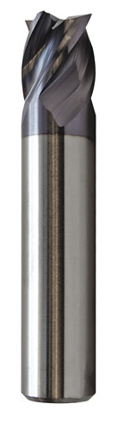
This 4-flute, high-performance endmill offers enhanced corner protection and enhanced geometries, according to M.A. Ford.
When optimized for an application, the resulting endmill won’t be the lowest-cost tool but it will pay dividends. “When they say your tool costs more, I always ask, ‘Are you getting the same number of parts each and every time?'” DePerno said. “If not, that’s costing you a lot more money.”
Toolmakers, however, aren’t the only ones that play an active part in endmill optimization. The ideal customer, according to DePerno, establishes endmilling benchmarks. “It’s hard to improve when there are no measurements in place.”
When seeking an ideal endmill, Schmidt recommends end users to constantly look for better methods and solutions. “They are out there.” CTE
Glossary terms in this article
Related




Subscribers can use MFGAxis notes, saves and discussion tools with their innoNET account.


