Engineer-Speak
Engineer-Speak
Geometric dimensioning and tolerancing defines part geometry—and you should already know that.
 "If you're going to be a writer, you'd better understand grammar," Arthur Malechek said. "If you're going to be an engineer, you've got to understand the system that allows you to convey your design intent."
The veteran engineer and instructor is referring to geometric dimensioning and tolerancing (GD&T), a system of symbols, rules and definitions that define the geometry of mechanical parts. However, Malechek, technology training coordinator at Pueblo (Colo.) Community College, worries that too few in the manufacturing industry do understand GD&T.
"For some reason, many engineers don't have a good grasp of GD&T, nor do they seem to understand the urgency or the importance of learning it," he said. "My theory is that it's the result of a lack of hands-on training, because so many engineers go from high school to college to the workforce, learning the theory inside and out but not having any foundation from actually working in machine shops. They don't learn the practical aspects, which is really frustrating from my standpoint."
This lack of understanding goes beyond mere professional frustration.
Form, Fit and Function
According to the ASME Y14.5-2009 standard on dimensioning and tolerancing—the global standard—GD&T can more accurately define the dimensional requirements for a part, allowing, in some cases, a more than 50 percent greater tolerance zone than coordinate or linear dimensioning. Proper application ensures the part has the desired form, fit and function with the largest possible tolerances.
"In other words, it's a precise mathematical language that can be used to describe the size, the form, the orientation and location of part features," explained Tim Graves, owner of Dimensional Management Systems LLC, St. Clair Shores, Mich. "It's very easy to imagine a triangle, with GD&T at the center and design, manufacturing and metrology making up the three sides. GD&T doesn't affect only those tasks, it affects every aspect of an organization. It starts with the design engineer, but it affects manufacturing, the customer, processing, serviced parts, other divisions, purchasing, part service, plant layout, sales, reliability, inspection—many, many things."
However, this broad impact can lead to ample opportunities for serious misunderstandings.


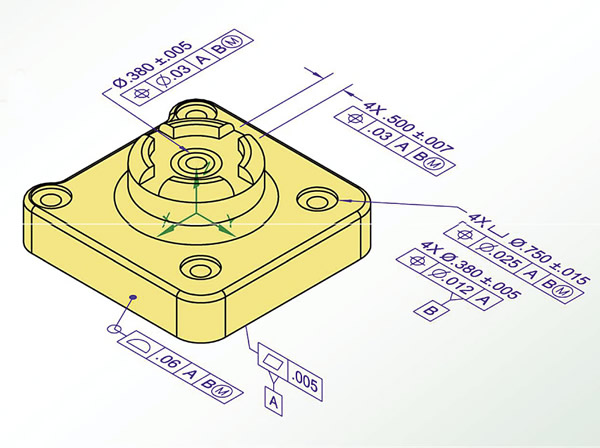
GD&T is a system that, when used properly, allows all features of a part to be described with perfect accuracy, ensuring the part's form, fit and function will work within an assembly. Image courtesy Bryan R. Fischer/Advanced Dimensional Management LLC.

"You can't quote a part if you don't know what you're looking at in the drawing," said Wendy Patterson, president of Fredonia, N.Y.-based training and coaching firm Tec-Ease Inc. Everyone, she said, from the designer to the person shipping the part out the door, should have at least a basic understanding of GD&T.
This includes purchasing agents, vendors and sales reps. Granted, not everyone needs to know how to apply GD&T to a drawing, she said, but if a job is quoted and the customer wants the job held to certain tolerances, the company will lose money if that's not communicated down the line.
According to Graves, GD&T even affects shop layout and processing. How, he asked, can somebody process a part if he doesn't know what the drawing means? How can a machinist know the proper machinery to use? Where should machine tools be put in relation to each other for maximum efficiency?
"Anybody who manufactures anything should be using GD&T, and a lot of companies just don't," he lamented. "It's what keeps us busy I guess, but it's not a good thing for the industry."
Ensure Benefits
The benefits of GD&T stem from the improved communication between all participants in an assembly's lifespan. According to Graves, it does this by keeping design, production and inspection speaking the same language, providing uniformity of drawing specifications and guidelines to interpretation, and giving designers a tool to specify exactly what they need. In addition, because it's a universal language, anybody—regardless of geography—can interpret a drawing correctly using GD&T. However, that language is only useful when everyone involved speaks it.
"A problem I see is that many of the people involved in GD&T come from a training or education background," said GD&T consultant John Eavey of DQAT Inc., Fort Wayne, Ind. "It's not that they don't understand the systems, because they absolutely do, but I grew up working hands-on in the industry for many years and came across GD&T from a place of practical necessity, not formal education. That means, as an instructor, I can put GD&T into terms that apply directly to engineering or inspection or manufacturing or assembly, because I've been there, I've done that."
In Eavey's experience, the best environment to learn the language is in in-house seminars with individuals who perform different functions at a company. This is because a closed group of engineers, designers or manufacturers will typically agree with each other as far as the interpretation and application of GD&T. And this is not necessarily a good thing.
"You can't intelligently dimension and tolerance a part in a vacuum," he said. "You have to know where it goes and what the function is, and that function is what drives how the part is dimensioned and toleranced by the engineer."
While manufacturers and inspectors may prefer the engineer to dimension parts the way they will be manufactured or inspected, Eavey continued, the engineer's job is to design a part that will function; the job of manufacturing and inspection is to determine how to meet those specifications.
"If a part in your car breaks, the replacement part had better fit—that's the function," he said. "An engineer's job is to make sure the part will function when it's done. The beautiful thing when you teach that in a mixed class is that you wind up with a lot of red faces and torqued jaws, because they're used to engineering doing that part of the job for them, and they really shouldn't be. Having a mixed class like that is excellent, because you get guys arguing with each other about what the system really means, which leads them to learn and understand more than they would otherwise."
The Tec-Ease philosophy is similar, according to Patterson. Everyone is taught the fundamentals, with specialized courses for different personnel. "The use of symbols allows you not only to design the part, but to document—on the drawing—what needs to be made in order to ensure parts fit together," said Luis Aguirre, Tec-Ease's GD&T coach. "You do that by taking advantage of the 14 symbols in the ASME standard, and if you use the hierarchy—an organizational system Tec-Ease uses—it almost guarantees that you're going to get a cost-effective part every time. No other method I've been introduced to has been able to do that."
Software vs. the Hard Way
But wait, can't you just plug the information into some software and let computers do the heavy lifting?
"GD&T is not like a computer program where you learn the interface, you learn the rules and then you can run the program. It's really about learning and understanding design, dimensioning and, of course, how parts fit together," said Tec-Ease's Aguirre. "Once you understand that concept, then we can start talking about the symbols."
When Aguirre began teaching, he came to realize that a lot of people don't even understand the concept of design intent—part drawings were frequently defined by plus/minus dimensions.
"That's easy and looks good and can be largely handled by computers, but the problem is that, at the end of the day, all of the plus/minus dimensions would be met for each part feature, but the parts didn't go together because tolerances stack up at assembly. As a designer or engineer, I'm going to draw my CAD model, but the program isn't automatically going to put GD&T on the drawing. I need to have knowledge of how that works in order to apply it correctly."
While many CAM packages have GD&T symbols available, the software can't apply the correct symbol to each feature of the drawing. Some of the more advanced packages can identify an incorrect symbol, but that's as far as it goes, according to Pueblo Community College's Malechek.
SolidWorks has a package that will analyze the assembly, he added, but the GD&T symbols must be applied directly to the CAD model, not just the drawing, in order for the software to make sense of it.
Standard Interpretation
While ASME standards are typically U.S.-specific, the constantly evolving nature of ISO standards, paired with the sheer number of ISO standards applicable to GD&T, has led to the global adoption of ASME Y14.5-2009.
"While the ASME standard is based around design intent, the ISO standard is based on instruction and inspection, primarily," explained Tec-Ease's Patterson. "We have trainers in England, China and Brazil, and they all use translated versions of the ASME standard."
Indeed, Malechek has been teaching GD&T to the ASME standard for nearly 20 years, and at least one thing has remained constant.
"I started teaching the 1994 standard," he said, "and while there are some fundamental differences between that standard and the 2009 version, the one thing I've always seen is that people on the shop floor really want to understand what I'm teaching, so they can make sure that they're designing, manufacturing and inspecting the parts they way they're supposed to."

What Is It?
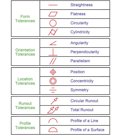
Essentially, GD&T is a universal language comprised of symbols and mathematical equations which, when used properly, allows a part to be described in terms of geometric perfection, regardless of who is describing it. The language describes geometry through these 14 primary symbols, as well as many other secondary ones.

Illustration courtesy Bryan R. Fischer/Advanced Dimensional Management LLC.

Contributors
Dimensional Management Systems LLC
(586) 772-8646
www.dmsgdt.com
DQAT Inc.
(260) 489-7712
[email protected]
Pueblo Community College
(866) 478-3256
www.pueblocc.edu/tec
Tec-Ease Inc.
(888) 832-3273
www.tec-ease.com


