Flute insurance
Flute insurance
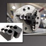
Engineered coating combinations control heat and keep chips flying in dry-drilling operations.
Courtesy of Tri-County Record/Myron J. Schober Engineered coating combinations control heat and keep chips flying in dry-drilling operations.
A cooling flow of metalworking fluid can be a significant contributor to machining productivity. The coolant reduces cutting temperature, provides lubricity and aids chip evacuation. However, the cost of coolant, growing environmental concerns about coolant disposal and chip recycling considerations are prompting many shops to look at dry machining or minimum-quantity-lubrication alternatives.
The viability of machining dry depends on several factors. The characteristics of some workpieces can make dry machining impractical; machining materials that dissipate heat poorly, workharden quickly or are gummy may mandate coolant. The nature of the metalcutting operation being performed plays a role, too. While chip formation occurs unimpeded in milling and turning operations, when drilling, the tool, chips and heat are buried in the workpiece.
Bob Hellinger, national sales manager for toolmaker Guhring Inc., Brookfield, Wis., said operating dry to maximize heat transfer to the chip can be beneficial in some turning operations, "but in drilling that heat is going to stay more in the tool." The heat can weld workpiece material to the drill and later cause tool failure.
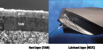
Courtesy of Dennis T. Quinto
The combination of a lubricious coating (in this case WC/C) deposited on a hard coating (TiAlN) facilitates dry drilling as the hard coating resists cutting edge wear while the softer, lubricious coating on the drill flute behind the actual cutting edge facilitates chip flow across the flute and out of the hole.
Despite the challenges of drilling dry, Hellinger said, the process and its close relative, MQL drilling (see sidebar, next page), is catching on for aluminum and cast iron applications. "Automotive is heavily into those materials and they've gone to dry and MQL drilling for the benefits of reducing coolant," he said, adding that coatings are essential when dry drilling is feasible.
Soft and Slick
According to Dr. Dennis T. Quinto, a surface engineering consultant and cutting tool industry veteran, a major development in dry drilling coatings has been the addition of relatively soft coatings with self-lubricating qualities. The coatings typically are tungsten-carbide/carbon (WC/C), diamond-like amorphous carbon (DLC) or molybdenum-base materials.
"Soft" is a relative term; traditional hard coatings such as titanium carbonitride (TiCN) or titanium aluminum nitride (TiAlN) may exhibit hardness of 2,000 to 3,000 HV, while the self-lubricating coatings are 500 to 1,200 HV. Quinto said a softer coating is usually applied over a hard coating.
"You are dealing with an optimized physical vapor deposition (PVD) coating, then you put a WC/C, DLC or molybdenum-base material on top of it," he said.
When applied over a hard coating, the lubricious coatings do two things. First, they decrease the friction at the cutting edge and mitigate the "running-in" phenomenon. In the first few seconds or minutes of a cutting operation, there often is a rapid increase in wear—a running-in period—after which wear tapers to a milder and more gradual pace. "In that initial period, that soft layer can lower cutting forces," Quinto said. "Then, after the softer layer has worn away, the harder coating basically does its thing."
The lubricious coating's second function, expediting chip ejection, is key to dry drilling. "After a chip is formed, it has to get out to avoid chip jamming," Quinto said. A lubricious soft coating on the drill flute behind the actual cutting edge facilitates chip flow across the flute and out of the hole. The coating lasts longer on the flute than on the cutting edge because there is not much abrasive wear occurring in the flute area, according to Quinto.
Like Teflon
Guhring's Hellinger said his company began working with the German government about 10 years ago to reduce coolant use in machining. "The first true dry-machining coatings we developed consisted of a multilayer TiAlN and TiN coating topped with a molybdenum-disulfide-style coating for lubricity," he said.
The coatings are applied via PVD. The coating sequence for the hard multilayer base coating, which Guhring calls Firex, begins with a layer of TiN followed by a layer of TiAlN, then progressive layers of TiN and TiAlN. "That's where you get the benefits of abrasion resistance and heat resistance, because that material oxidizes at 1,470° F," Hellinger said. Conversely, he thinks of the molybdenum-disulfide top layer, called MolyGlide, "in terms of Teflon." It doesn't perform the abrasion-resistance function of a hard coating, but "put it on top of any coating or substrate and it will keep material from sticking to it," he said. "It eliminates built-up edge and keeps the chips flowing; it acts like a lubricant would."
Regarding comparative coating performance, Hellinger cited the example of an 18mm-dia. drill making 50mm-deep holes in cast iron. A TiAlN-coated drill, run dry at 100 sfm and a 14.7-ipm feed, was able to complete 400 holes before regrinding was necessary. A Guhring drill of the same diameter and featuring a Firex/MolyGlide multilayer coating, run at the same parameters, produced 1,200 holes before regrinding. Although the cost of the replacement drill was about 30 percent higher than the original, regrinding and downtime costs incurred with the original drills due to their shorter life were three times higher than those of the Firex/Molyglide-coated replacements.
Guhring recently introduced a nanolayered version of the Firex coating with approximately 80 nanoscale layers in its 1.5µm to 5µm total thickness. "Each layer is thinner, and that helps because if you have crack propagation, it takes a lot more shock to bring it down to the base substrate material," Hellinger said.
PVD Advantage
Dennis Quinto said the PVD process used to apply the coatings is advantageous because it provides an ability to "mix and match layers; you can design layers of these coatings down to a very thin dimension, typically as low as 20nm to 30nm. Any time you can modulate the composition and structure it, you can engineer more toughness into the coating."
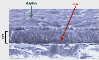
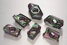
Courtesy of Guhring
Guhring Inc. developed a coating for dry machining consisting of a multilayer TiAlN and TiN coating (called Firex) topped with a molybdenum-disulfide-style coating (called MolyGlide) for lubricity.
Modulation of coating layer thickness is the focus of a recent upgrade of a DLC coating from Sumitomo Electric Carbide Inc., Mt. Prospect, Ill. Rich Maton, the toolmaker's assistant engineering manager, said the initial version was a stand-alone coating (not as a final coat over a traditional hard coating) for cutting aluminum and other nonferrous materials.
"While you are shearing aluminum, the chip is continually sliding across the face of the insert," he said. "Aluminum is very abrasive and would start generating heat." The DLC coating reduces the coefficient of friction between the workpiece and tool.
The new version of the coating employs more layers built to a greater final thickness. The previous version's total thickness was 0.05µm to 0.1µm, while the upgraded coating is 0.4µm to 0.5µm thick. Earlier attempts at producing a thicker coating resulted in inconsistent adherence of the coating to the tool. Maton said Sumitomo has developed technology to stack thinner DLC layers to a greater final thickness while improving its bond to the substrate.
According to Maton, the updated coating provides both lubricity and increased abrasion resistance. "By thickening the coating, we are adding more wear resistance," he said.
He noted that the original coating was a shiny metallic blue, and the new version is more of a gold and green. "Changing the [number of] layers of the coating changed the prismatic feature of the color itself."
The updated coating still improves lubricity. "We have an H1 carbide that is a high-polish uncoated carbide we use for aluminum. When we add the DLC coating (grade DL1000), the surface is so smooth that the chip not only easily flows across it, but the surface now also has greater lubricity and a reduced coefficient of friction," Maton said. Increased tool life in abrasive situations is another result. "Not only are your chips not going to stick to your carbide insert, but now you get more wear resistance," he said.
Dry Heat
The key to dry drilling is control of tool-degrading heat. TiAlN and AlTiN coatings possess higher heat resistance than TiN coatings because the aluminum forms an aluminum-oxide film during machining that acts as a heat barrier and promotes heat transfer into the chip rather than the tool. Toolmakers have recently developed coating materials that include chromium and silicon to further strengthen that heat barrier via formation of chromium and silicon oxides.
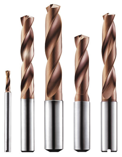
Courtesy of Oerlikon Balzers
These drills are coated with the multilayer AlCr-based Balinit Helica from Oerlikon Balzers; the company says the coating's hardness, resistance to oxidation at high temperatures and its low coefficient of friction make it beneficial for dry drilling.
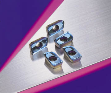
Courtesy of Sumitomo Electric Carbide
An update of Sumitomo's DLC coating involving deposition of more layers to a greater final thickness changed the prismatic characteristics of the coating surface, resulting in a gold/green look to the updated coating (bottom), compared to the original metallic blue (top). Turning inserts are pictured to better show the color difference.
Thomas Schattauer, senior manager of sales administration for Oerlikon Balzers USA Inc., Elgin, Ill., cited his company's multilayer AlCr-based Balinit Helica coating as especially well suited for dry drilling because it offers high hardness at typical drilling temperatures and provides oxidation resistance to 2,000° F. It also possesses a low coefficient of friction (0.25) against dry steel, aiding chip ejection.
Schattauer noted that appropriate feed rates are critical in dry drilling to ensure heat is removed by the chip. Too light a feed limits the amount of heat the chip absorbs, permitting it instead to flow into the tool and hasten its failure. He said many shops think ultraconservative parameters are required to succeed in dry drilling, but to make the high-performance coatings work, cutting parameters need to be on the aggressive side. Balinit Helica can permit feed rates to be increased in the range of 30 percent compared to those applied with uncoated drills, according to Schattauer.
Fast Plasma
A Minnesota company has introduced a coating technology that may boost productivity in dry drilling. Rushford (Minn.) Hypersonic LLC was founded in 2007 to commercialize the Hypersonic Plasma Particle Deposition (HPPD) coating process developed and patented by the Mechanical Engineering Department at the University of Minnesota. The process combines chemical vapor deposition with plasma deposition of nanoparticles from 4nm to 40nm at hypersonic speed: 2,400 m/sec. and faster. According to the company, as the particles impact the surface at eight times the speed of sound, a phase change in the nanoparticles upon impact causes them to infiltrate and bond into the substrate, as opposed to simply coating the surface. The coating's hardness ranges from 36 to 50 GPa and its fracture toughness is approximately 6 MPa, according to Rushford. Silicon, carbon and silicon-carbide coatings have been produced by injecting vapor-phase silicon and hydrocarbon precursors into an ArNH2 plasma, the company reported.
President and CEO Daniel Fox said the coating consists of a single layer approximately 1µm to 10µm thick, depending on the application requirements. Because the coating components bond with the base material, he said, "you have to rip out part of the substrate to get our material off."
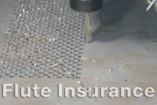
Rushford Hypersonic recently commissioned the machining division of Connaughty Industries, also based in Rushford, to perform a series of tests comparing the performance of 0.250 "-dia. HSS drills coated via the HPPD process to that of uncoated drills from the same manufacturing lot. The test material was 0.5 "-thick 304 stainless steel plate, and hole locations were not center-drilled. After a break-in period consisting of drilling 40 holes at 370 rpm and a feed rate of 1 ipm with a 0.100 " pecking cycle, the drills were run at 600 rpm and a feed rate of 1.5 ipm, with a 0.050 " peck. All tests were performed without coolant (see photo on page 35).
Connaughty Industries reported that an HPPD-coated drill completed 1,480 holes before edge chipping occurred. The coating, however, appeared to be intact. Drilling continued until the drill failed due to fracture of the cutting edge, with the HPPD coating still intact, in the 1,547th hole. The first hole drilled measured was 0.253 " in diameter, and the last was 0.2495 ".
The best-performing uncoated drill completed 233 holes. The uncoated drills failed when the cutting edge folded under, overheated and fractured, according to Rushford. The first and last holes drilled with the uncoated drills were 0.250 " in diameter.
Fox said the goal of these initial tests was "to take the least expensive drill bit, coat it and see what the life expectancy would be." The company is beginning tests of the coating in milling operations. Fox added that applications of HPPD coating are not limited to cutting tools and include wear reduction in dies, pultrusion equipment, bearings, cams, cylinder walls and implantable medical devices.
Apply as Required
Any potential dry-drilling application represents a mix of tooling, workpiece and part characteristics and requirements. Other factors are involved as well; for example, Sumitomo's Maton said the decision to go dry could be based on part volume. "If we are going to plunge a high volume of holes as fast as we can, typically coolant would be applied, but if it was an environment that is not as high production, then we could drill dry," he said. "There has to be a tradeoff."
However, when factors are weighed and the decision is made to eliminate or minimize coolant, toolmakers have and will continue to develop coatings that enable shops to maximize productivity. CTE
About the Author: Bill Kennedy, based in Latrobe, Pa., is contributing editor for Cutting Tool Engineering. He has an extensive background as a technical writer. Contact him at (724) 537-6182 or by e-mail at [email protected].
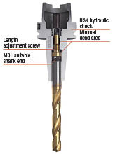
Courtesy of Guhring
MQL employs a fine mist of coolant that must be directed into the back of the tool to avoid loss. Guhring has developed an MQL toolholder delivery system that involves a special tool shank and adjustable components within the holder to channel and conserve the lubricant during MQL.
Nearly dry drilling 'a whole different animal'
An intermediate step between traditional coolant-based machining and totally dry machining is minimum quantity lubrication. In MQL, coolant is supplied as a fine mist, with fluid flow rate in the area of 30 ml/hr. to 500 ml/hr., compared to traditional flood coolant flow of perhaps 10 l/min. Shops using MQL typically employ environmentally friendly vegetable oil or ester oil to provide lubricity.
According to Guhring's Hellinger, "MQL is a whole different animal" in the way coolant is delivered. "You have so little coolant going to the cutting edge, you have to make sure it gets there. Because it is a fine mist, if you don't direct it correctly into the back of the tool, you are going to lose some of it. So you want to get the correct geometry to get it to mate up to the MQL toolholder delivery system."
As a result, he said, the shanks of the tools Guhring provides for MQL applications are different than those of standard tools, and the back of the tool features a taper or a cone. "We have a couple proprietary designs on some HSK holder designs that are specifically for MQL applications," Hellinger said. "The tools typically are aimed at high-volume transfer lines that are going into automotive plants; they use that type of holder now because they are much more efficient at delivering coolant in MQL volumes."
—B. Kennedy
Edge prep crucial to postponing tool failure
The cutting edge a coating covers is as important as the coating, according to Bill Shaffer, executive vice president of microedge preparation provider Conicity Technologies LLC, Cresco, Pa. "Coatings are only half of the story; the cutting edge still must be properly prepared to delay the failure mode of increased tool pressure/heat. The two technologies must work together," he said.
Shaffer explained that cutting edge problems in dry drilling appear as the number of holes increase. "The wear on a drill is located on the front flank of the cutting edge or on the intersection of the primary relief and the cutting edge," he said. "The cutting edge breaks down, creating a flat on its face. As the flat grows, the pressure required to make the tool cut increases." Increased tool pressure equates to higher tool temperatures and eventually to tool failure.
Also common in dry drilling is built-up edge. A combination of high tool pressure and high chip temperature will cause the material to collect (or weld) to the edge. "If you can keep the temperature down, chip welding will not take place," Shaffer said.
To minimize both problems, Conicity recommends properly sized edge preparation. "It has to be a controlled size that is large enough to strengthen the corner, but small enough that the drill still wants to cut like the edge is sharp," Shaffer said.
—B. Kennedy
Contributors
Conicity Technologies LLC
(877) 752-6132
www.conicity.com
Guhring Inc.
(800) 776-6170
www.guhring.com
Oerlikon Balzers USA Inc.
(800) 792-9223
www.oerlikon.com/balzers/us/
Dr. Dennis T. Quinto
(716) 983-1377
[email protected]
Rushford Hypersonic LLC
(866) 730-4773
www.rushhypersonic.com
Sumitomo Electric Carbide Inc.
(800) 950-5202
www.sumicarbide.com