

Plan ahead
Presented here are more tips and tricks for proper planning when CNC machining. One of the first and simplest things to look for when performing operations that involve vises is the length of the contact area between the part and the vise jaws.
Presented here are more tips and tricks for proper planning when CNC machining:
- One of the first and simplest things to look for when performing operations that involve vises is the length of the contact area between the part and the vise jaws. In general, choose the longest contact area possible. Figure 1a shows a setup made as rigid as possible before any material is removed. Initially, aggressive cuts can be made with high feed rates to remove material. As the “window” cut (Figure 1b) nears completion, the part becomes much weaker, and lighter cuts must be taken. These types of machining scenarios are common and must be planned in advance.
- Rigidity is important. As you envision or simulate material being cut away, think about the rigidity of the part and setups. When possible, choose a sequence where you can apply short, sturdy endmills. Long endmills are sensitive and less forgiving of higher feeds and speeds than short ones. They usually need to be run slower. Long endmills have a tendency to chatter and push away. If you need to apply long tools to cut tall or deep features, sequence the setups so that the long endmills are run when the workpiece has the most rigidity. If you use long endmills on a part that has already been weakened by previous machining, you’ll likely compound difficulties.
- Planning begins by visualizing the different ways you can hold a part for each setup. As you think about the different possible setups and machining operations, keep track of what material remains on a part that can be used to hold the part for future setups, and also what material remains so you don’t run into any uncut material by mistake. Some parts may not have simple solutions. Look for a sequence that uses the fewest number of setups. Multiple setups take time and are ripe for inducing dimensional errors. CAD systems help you visualize all the possible holding combinations because you can easily flip and rotate the model on the computer screen. In general, I prefer using as few setups as possible when doing a job, even at the expense of having to run long endmills less aggressively or cutting angles by 3D milling.

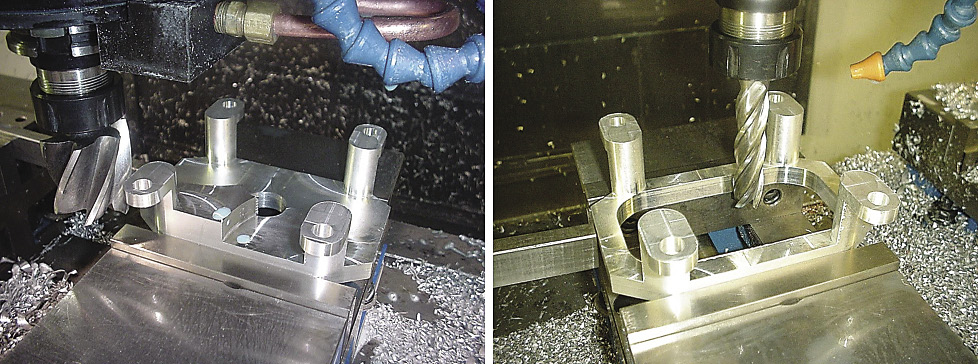
Figure 1a (left): This setup was chosen based on using the longest contact area possible with the vise jaws.
Figure 1b (right): As the “window” cut nears completion, the parts become much weaker. Lighter cuts must be taken at this stage.
Images courtesy J. Harvey.
Review the print ads from this magazine to continue
This quick advertiser review unlocks the rest of the article and keeps the full-screen reader focused on the ads instead of the page chrome.
Advertisers included in this article experience
Print placements connected to this article
Gmail
staying sharp
Shop Technology machine requires careful planning and consideration these machines. Proper utilization of CAM software of key elements. requires training, which, like machine training, can be Multitask machines can have complex and expensive expensive and disrupt production. features, such as large tool magazines, probes, tool In addition, a significant amount of development.
staying sharp Shop Technology machine requires careful planning and consideration these machines. Proper utilization of CAM software of key elements. requires training, which, like machine training, can be Multitask machines can have complex and expensive expensive and disrupt production. features, such as large tool magazines, probes, tool In addition, a significant amount of development measurement systems and monitoring devices. These time often is needed to get the post-processor for the features allow users to maximize gains from the machine CAM software to where it will provide the desired CNC by limiting human interaction. code for the machine control. As machine complexity However, setup and learning to use these tools increases, so does the time needed to develop the
Visit Gmail View this placement in the issue recordPrint ads from this magazine
Shop Technology machine requires careful planning and consideration these machines. Proper utilization of CAM software of key elements. requires training, which, like machine training, can be Multitask machines can have complex and expensive expensive and disrupt production. features, such as large tool magazines, probes, tool In addition, a significant amount of development.
staying sharp Shop Technology machine requires careful planning and consideration these machines. Proper utilization of CAM software of key elements. requires training, which, like machine training, can be Multitask machines can have complex and expensive expensive and disrupt production. features, such as large tool magazines, probes, tool In addition, a significant amount of development measurement systems and monitoring devices. These time often is needed to get the post-processor for the features allow users to maximize gains from the machine CAM software to where it will provide the desired CNC by limiting human interaction. code for the machine control. As machine complexity However, setup and learning to use these tools increases, so does the time needed to develop the
Continue reading
January 2016
- Determine if you can machine a job holding the material in a standard milling machine vise. Use a vise when possible. A vise eliminates a lot of variables, including concerns about accuracy and rigidity of the workholding device. A high-quality vise is inherently accurate and rigid.
- Use multiple matched vises to hold long parts. Indicating multiple vises in line may take some time. However, once the vises are in place, they can usually be left alone for a while. Multiple vises can be used to run multiples of the same part with different starting points, such as G54, G55 or G56.
- Determine how you are going to square the material. Squaring the five sides of a part that are accessible in a setup means you must side-mill four sides. The top surface can be facemilled. Side-milled surfaces are more prone to inaccuracies than facemilled ones. An endmill used for side milling that is dull, chipped or tapered will impart a poor finish. This is especially true for long endmills. Therefore, to ensure accuracy when side-milling a surface, apply a new endmill.
- Square large, tight-tolerance parts independently. In other words, concentrate on getting good blanks first, then use other programs to add the necessary features.
- Plan for material warpage. Warpage is a fact of life when machining; it is often an issue that must be addressed, especially with long, slender and hogged parts. It may not be much of an issue on stocky, blocky parts or parts that need just a few simple features. One of the most effective ways to eliminate the tendency of material to warp is to cut through the skin of the stock material before doing any other precision machining operations.
About the Author: James A. Harvey is a machinist and plastic moldmaker who has worked in shops across the U.S. for nearly 40 years. Harvey’s column is adapted from information in his book “CNC Trade Secrets: A Guide to CNC Machine Shop Practices,” published by Industrial Press Inc., South Norwalk, Conn. The publisher can be reached by calling (888) 528-7852 or visiting www.industrialpress.com. By indicating the code CTE20OFF when ordering, CTE readers will receive a 20 percent discount off the book’s list price of $29.95.
Related




Subscribers can use MFGAxis notes, saves and discussion tools with their innoNET account.


