Tips for controlling runout
Tips for controlling runout
Runout can cause a host of problems; make minimizing it a priority.
Machinists struggle with different problems during the day like materials that are hard to machine, tight tolerances, programs that don't make any sense and the safety guy who is always finding something wrong. Of course, there are many other things that can go wrong, but most of our machining aggravations occur only occasionally.
Unfortunately, we also face a few constant problems, and runout is one of those that machinists fight regularly.
Runout is rotational deviation of one feature relative to another. Consider the motion of a crank shaft and its crank pins. This motion is a good way to visualize runout. When a crank is rotated about the journals the crank pins swing in a path that rises and falls relative to the center of the journal. Runout in a shaft or a cutting tool has a similar motion.
So why is runout a problem? It can cause alignment issues in rotating components leading to bearing failures, bad seals and out-of-balance conditions. Runout in cutting tools causes tool breakage, out-of-balance conditions, over-size holes, bad surface finishes and machine failures. So, minimizing runout is important.
When creating specifications for new components engineers give a significant amount of consideration to runout and the effects on machinery. That is why we see tight tolerances on drawings. It is common to see a drawing that has a runout requirement less than 0.0005" between two or three features.
Runout issues are most common on turning because parts made on a lathe are often rotating parts or parts that combine with rotating parts. Therefore, engineers will include runout tolerances to control geometric and rotational characteristics.
The first step to controlling runout at the lathe is building a process that negates the errors that are inherent to turning processes. Although obvious, it must be noted that success requires using a lathe that is well-serviced, operating correctly and accurate enough to hold the tolerances. If the lathe spindle is running out 0.0005" then the best part runout you can hope for is 0.0005".
Assuming the machine is accurate and capable the next step is to build a turning process that negates any of the inherent errors in the machine and the workholding. When possible, machine every critical feature without removing the part from the machine. Doing so will ensure the errors that exist in the workholding device are negated. No workholding device is perfect; they all have some runout that will be introduced into the system. This is why you see machinists turning (or grinding) between centers.
Often, parts must be "flipped" over to complete the machining process. So, the third step is selecting the right workholding method. It is impossible to say that one method is better than another. The best workholding is going to depend on the conditions of the job, the machine, the shop, the material, etc. For production quantities on modern CNC turning machines a good hydraulic three-jaw chuck is sufficient for most jobs. Machined soft jaws that match the diameter of the part are often good enough to meet the drawing requirements. Depending on the machine, material and skill of a machinist, 0.001" to 0.002" runout can be held with a three-jaw. Once the runout requirements get to 0.001" or less a collet chuck is the best choice. Consistently holding 0.0005" runout with a quality collet chuck is not a problem. This is why high precision tool room lathes come standard with a collet chuck and the three-jaw is sold as an option.
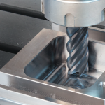
Runout on turned parts almost always shows up as a dimensional problem. Runout in milled parts can manifest itself in numerous ways, including dimensional issues, poor surface finish, early tool wear and chatter.
Again, a well maintained and accurate machine is the first step to combating and eliminating runout. If the milling spindle is sloppy, there is nothing that can be done to overcome it. Every tool placed in the spindle, at a minimum, will have the same amount of error as the spindle.
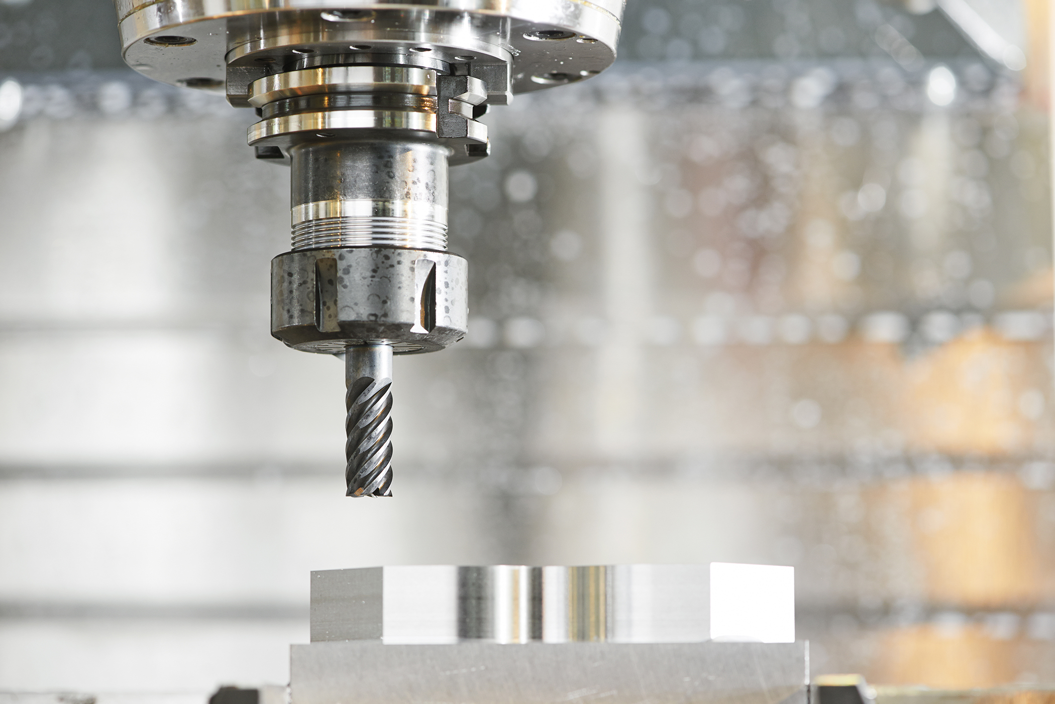
Selecting the appropriate toolholder is the next step. This is one of those machining topics that can ignite some serious debates. I have had tool manufacturers tell me they would not warranty tools or guarantee a process if I were not using a specific type of toolholder. The best advice is to use the holder that is best for the job. If you are drilling 0.500" holes in hot roll plate with a +/-0.030" tolerance, then a state-of-the-art toolholder is probably not necessary. If you are milling the final details in a die set that is worth $100,000 using a 0.0625" diameter endmill that is 6" deep in the pocket, you should probably be using the best toolholders money can buy. It's all about risk.
Like all things in machining, there are lots of toolholders to choose from. For most milling work a collet chuck is going to be sufficient. ER style collets are the predominant technology today and runout of a standard issue collet and collet chuck is 0.0004" to 0.0008" depending on the grade and manufacturer.
If the holder is running out 0.0004" at face, then the end of a long tool is likely running out a lot more. It is difficult to ream a hole that has a 0.0005" tolerance with a reamer that is running out over 0.0004". More precise holders are needed in these situations. Sometimes this can be overcome by purchasing a "precision" collet and toolholder rather than the "standard" grade.
Other times the tool can be adjusted. Turning the tool in collet will sometimes displace the "bad" spots on the collet and the tool and provide acceptable runout. I have shimmed between the tool and the collet to give acceptable results, but I only do this when it is absolutely necessary. It also is possible to purchase adjustable toolholders that allow the user to compensate for axial and radial runout of a tool. These toolholders allow the user to dial out all of the runout.
As you probably expect, adjustable toolholders are expensive and can be finicky. They are typically reserved for high production environments like automotive manufacturing. A simple cost-effective way to get adjustability in a pinch is to use a boring head. While it might take some finagling to get the tool mounted, it does allow the user to remove radial runout from tools like reamers. Running a reamer in a boring head looks wonky, but it is effective.
Milling holders are the best option for endmills. These holders use a collet but unlike ER and similar styles, these collets are size specific. Mill holders are reasonably accurate at 0.0005" runout and provide the grip strength needed for aggressive milling, but they are beefy and it can be hard to get them in confined spaces.
Heat shrink holders are the most accurate option available for milling. Heat shrink holders can repeatably drive runout into the 0.0001" range. Not only do they provide the best runout characteristics they also provide the strongest grip. When accuracy is paramount, heat shrink tooling is the first choice.
As expected, they are expensive and require expensive hardware to heat the holder and set the tool. The life of these holders is limited by the number of heating cycles they can endure, whereas a collet chuck has an indefinite life.
There are many solutions to runout, probably as many as there are machinists in the world. The biggest mistake inexperienced machinists make is not recognizing runout as the problem. Checking the setup for runout is one of the first things a person should do when issues arise.