

Wheel quality control: Inspection Efficiency
An inline, noncontact measurement system for 100 percent inspection of vehicle wheels.
Before vehicle wheels roll into the market, up to 80 geometric features relevant to their function, such as radial and axial runout, width and diameter, are typically inspected randomly with tactile measurement devices under laboratory conditions away from the production line. The procedure consumes about 45 to 60 minutes per wheel, making 100 percent inspection of the wheels impossible.
The “Wheelinspector” overcomes those inspection obstacles, reports the Fraunhofer Institute for Factory Operation and Automation IFF, which developed the measurement system with Ascona GmbH, Meckenbeuren, Germany, a manufacturer of optical profile measurement systems.
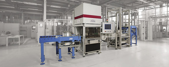
Courtesy of Fraunhofer IFF
The “Wheelinspector” makes noncontact measurement of vehicle wheels directly in the production process.
“The system makes fully optical, noncontact measurement of light- alloy wheels directly in the production process possible for the first time,” said Ralf Warnemünde, deputy manager of the measurement and testing technology business unit at Fraunhofer IFF. “Immediately after they have been machined, that is, turned, milled and drilled, the new 3-D laser technology compares finished products with their 3-D CAD model. It scans a multitude of geometric features and, with a cycle time of 20 seconds to inspect one wheel, can be fully integrated into the production flow.”
Review the print ads from this magazine to continue
This quick advertiser review unlocks the rest of the article and keeps the full-screen reader focused on the ads instead of the page chrome.
Advertisers included in this article experience
Print placements connected to this article
Kyocera’s M-Series
The latest members of
Milling Cutter Arsenal The M-Four and M-Six Milling Cutters featuring double-sided, thick edge inserts and long lasting MEGACOAT NANO Grades for superior performance t oug h pre c ise unchallenged Experience the M-Series Difference The M-Four and M-Six Milling Cutters are now available as part of the Kyocera Milling Kit Sale
The latest members of Kyocera’s M-Series Milling Cutter Arsenal The M-Four and M-Six Milling Cutters featuring double-sided, thick edge inserts and long lasting MEGACOAT NANO Grades for superior performance
Visit Kyocera’s M-Series View this placement in the issue recordPrint ads from this magazine
Milling Cutter Arsenal The M-Four and M-Six Milling Cutters featuring double-sided, thick edge inserts and long lasting MEGACOAT NANO Grades for superior performance t oug h pre c ise unchallenged Experience the M-Series Difference The M-Four and M-Six Milling Cutters are now available as part of the Kyocera Milling Kit Sale
The latest members of Kyocera’s M-Series Milling Cutter Arsenal The M-Four and M-Six Milling Cutters featuring double-sided, thick edge inserts and long lasting MEGACOAT NANO Grades for superior performance
Continue reading
June 2013
In addition, the institute stated that deviations of parts resulting from tool wear or breakage are reported to the machines immediately, preventing serial defects and cost-effectively optimizing production processes.
The basis of the measurement system is the OptoInspect 3-D technology developed at Fraunhofer IFF. The system projects laser light and measures points and lines through triangulation. A camera registers the projection light reflected diffusely by the parts. Based on that perspective, the laser projection in the camera image changes according to the wheel’s shape.
The measurement system includes four sensors and axes for moving and positioning the sensors during measurement. The institute explained that after wheels are moved into the measuring unit on a conveyor, they are centered and mechanically locked into place. An image-based identification system recognizes the wheel type and transmits specific feature information to the measuring unit. These coordinates are used to align each of the positioning axes of the sensors to their correct positions. The sensor cluster revolves around the wheel 360° and scans the measured values.
For more information about Fraunhofer Institute for Factory Operation and Automation IFF, Magdeburg, Germany, call +49 391-4090-0 or visit www.iff.fraunhofer.de. CTE
Glossary terms in this article
Related




Subscribers can use MFGAxis notes, saves and discussion tools with their innoNET account.


