


Four Thread-Turning Infeed Methods
The infeed strategy controls chip flow, cutting load, tool wear and cycle time.
The infeed strategy controls chip flow, cutting load, tool wear and cycle time.
Cutting a thread on a lathe is never a single-pass operation. The thread profile is too deep to remove at once, so the cut is divided into multiple passes. One question programmers can overlook is how the insert should approach the workpiece on each pass. This choice, called the infeed method, controls chip flow, cutting load, tool wear and cycle time. Pick the wrong method and you may encounter stringy chips, chipped corners and short insert life. Pick the right one and the same insert can run the whole batch.
This article covers four common infeed strategies used in thread turning: radial, flank, modified flank and alternating flank. It explains how each method loads the cutting edge, affects chip control and fits different shop-floor applications.
Why Infeed Method Matters
A threading insert has a full V-shaped profile. Depending on the infeed direction, a pass can engage one flank, both flanks or primarily the nose. When both flanks cut at the same time, they produce a stiff, V-shaped chip that is difficult to evacuate, and heat concentrates at the insert tip. When one flank does most of the cutting, the chip behaves more like a conventional turning chip and flows away more easily, but edge loading becomes asymmetric.
Selecting an infeed method therefore requires balancing chip control, cutting load and edge wear. Control capability matters, too: Not every CNC control or canned cycle supports every method.
Radial Infeed
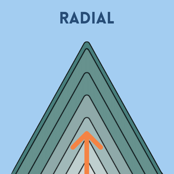
Radial infeed advances the tool straight along the X-axis, so both insert flanks cut on every pass. It is the most basic method, is broadly available on CNC controls and can be used on a manual lathe.
The primary drawback is chip control. When both flanks cut at once, they produce a V-shaped chip that resists evacuation, and the insert tip is exposed to more heat. Cutting forces are high, so the method may require more passes and extend cycle time. Radial infeed also limits the effectiveness of chip-forming geometries because the chip is constrained on both sides.
Use radial infeed for fine-pitch threads and short-chipping materials, such as brass and free-machining steel, when chip evacuation is not a problem. Because both flanks share the work, wear is distributed evenly across the cutting edge.
Flank Infeed
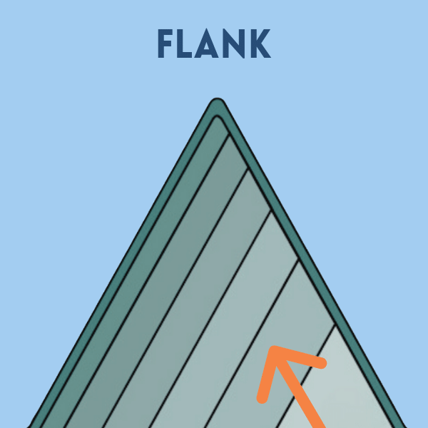
Flank infeed advances the tool along one thread flank at the angle of half the included thread angle—for example, use 30 degrees for a 60-degree thread. The leading flank performs most of the cutting, so the chip forms more like a conventional turning chip and flows away from the cut.
Flank infeed is a practical general-purpose choice that runs on all controllers. Improved chip formation permits chip-forming insert geometries, deeper cuts per pass and shorter cycle times. Loading one side of the edge also reduces the tendency to vibrate compared with radial infeed. The tradeoff is asymmetric wear. One flank does most of the work and wears faster, while the trailing edge can rub the freshly cut surface. Flank infeed suits coarser pitches (below approximately 24 TPI) and trapezoidal profiles, such as Acme threads, but modified flank infeed is generally preferred when available.
Modified Flank Infeed
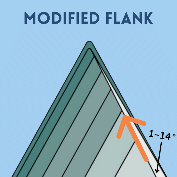
Modified flank infeed follows the same principle as flank infeed but offsets the approach angle slightly so the trailing edge clears the thread surface instead of rubbing it. The programmed value depends on the control and canned-cycle convention. For a 60-degree thread, the infeed is typically offset 1 to 5 degrees (maximum allowed, 14°) from the flank.
This small change improves chip control, reduces flank wear and lowers cutting load. When the control supports it, modified flank infeed is generally the first choice for many threading operations.
Alternating Flank Infeed
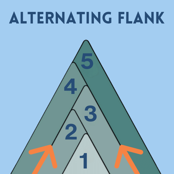
Alternating flank infeed switches the cutting side on every pass. The tool engages the left flank on one pass, the right flank on the next and so on. The work is distributed across both sides of the edge, so wear is even and tool life can improve. Cutting load remains lower than with radial infeed.
The tradeoff is that chips are directed to both sides over successive passes, which can complicate evacuation, and not every control supports the method. Alternating flank infeed works well for large, coarse threads (below approximately 5 TPI) with substantial material removal, where distributing wear across both flanks can extend tool life. On a heavy Acme or large trapezoidal thread, balancing the wear may mean the difference between completing the part with one insert or using several.
Selecting a Method on the Shop Floor
| Application Scenario | Recommended Infeed Method |
|---|---|
| Fine pitch, short-chipping material or manual lathe | Radial infeed |
| General threads on any controller | Flank infeed |
| General threads when the control supports modified infeed | Modified flank infeed (for improved chip control and tool life) |
| Large, coarse threads with heavy material removal | Alternating flank infeed (to distribute wear) |
On many CNC controls, the G76 canned cycle sets the infeed method as one of several parameters. Parameter meanings and allowed values vary by controller, so consult the machine or control documentation. For a G76 parameter breakdown and G-code generator, see the G76 thread cycle reference at machiningdoctor.com/gcodes/g76-thread-cycle.
Related

Subscribers can use MFGAxis notes, saves and discussion tools with their innoNET account.