Math matters: CMM Inspection
Efficient, productive machining involves many factors. Programmers, engineers and machinists need to master multiple important areas. Becoming adept at the use of key calculations is a critical matter.
Efficient, productive machining involves many factors. Programmers, engineers and machinists need to master multiple important areas. Becoming adept at the use of key calculations is a critical matter.
Students, apprentices and trainees receive considerable instruction on gauges, machine alignments and operation of machine tools but often get insufficient education about shop math. Smartphones, computers, CAM software and conversational controls almost have eliminated the requirement for students to learn the subject. Many people believe that technological advances minimize the obligation of craftspeople to understand and use shop math, as evidenced by the marketing of software and controls that generate information that once was calculated by machinists and toolmakers.
Given the power of today’s digital tools, reducing the instructional time spent on shop math is not warranted. There are calculations and geometric concepts that everyone associated with machining should master.
Speed Equation
Calculating the proper cutting speed is vital whether using a million-dollar vertical machining center or 50-year-old knee mill. When milling, the cutting speed is a function of rpm and tool diameter. Learning to express the cutting speed in terms of rpm or sfm enhances technical communication by giving common terminology to everyone. Being able to work backward from rpm to sfm allows a person to propagate efficient cutting parameters across a range of tool diameters. Using rpm to define the cutting speed of a milling tool is the same as using rpm to define the speed of a car—it has no meaning by itself.
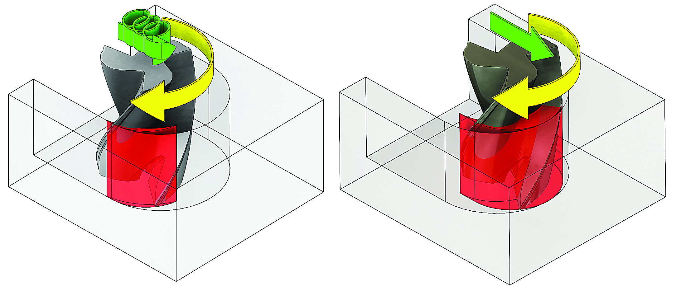
Understanding calculations associated with cutting speeds, feed rates and radial chip thinning enhances the use of advanced milling techniques, such as trochoidal milling. Toolpaths programmed with Mastercam’s Dynamic Machining suite produce radial chip thinning (left), whereas a traditional toolpath (right) doesn’t enable the productivity-enhancing benefits of radial chip thinning.
Once the cutting speed is established, the feed rate—the speed at which the tool traverses the workpiece—must be calculated. The most basic such calculation is: feed rate = rpm × the number of cutting teeth × the desired chip load, where the feed is expressed in ipm or mm/min. This is the “money” calculation because the feed rate is tied directly to the cycle time. A change in the feed usually is accompanied by a change in the cycle time, and feeding higher is almost always better for the bottom line.
Get Speeds and Feeds instantly based on dozens of parameters
Review the print ads from this magazine to continue
This quick advertiser review unlocks the rest of the article and keeps the full-screen reader focused on the ads instead of the page chrome.


MFGAxis Discussion