

Managing multiple milling constraints
The Machine Technology column from the April 2011 issue of Cutting Tool Engineering magazine suggests that successful milling requires managing multiple constraints.
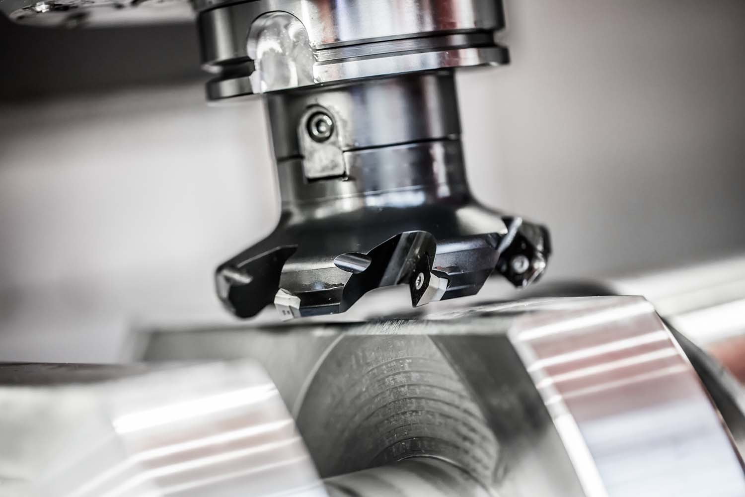
Milling is a complex process bound by multiple constraints. Successful milling requires selection of cutting parameters that respect the constraints. Presented here are explanations about six of those constraints.
Bending moment. The bending moment equals the cutting force times the distance from the cutting zone to the toolholder/spindle interface. If the bending moment is too great, the shank of a slender tool may break or separation can occur where the toolholder face contacts the spindle, allowing the toolholder to pull out of the spindle. That’s especially problematic for HSK holders because they derive their stiffness from the face contact. The bending moment can be reduced by shortening the tool or by reducing the cutting force, which requires reducing the axial DOC, radial WOC or the chip load. For most tools, the chatter limit is reached long before a shank breaks.
Chatter. Chatter generation is a limiting factor when milling, particularly when the objective is to have the metal-removal rate as high as possible. Chatter arises due to insufficient dynamic stiffness, which, in turn, is caused by long slender tools, small-diameter spindles (due to the DN limitation, where D is the diameter of the main bearing bore, and N is the spindle speed), thin workpieces (although a good machining strategy can usually avoid this) and the low-damping characteristics common in mechanical systems. Strategies to avoid chatter without changing the machine or tooling configuration include selecting the cutting conditions based on a stability lobe diagram, reducing the axial DOC and/or radial WOC and choosing a low spindle speed to enhance the process damping effect. Strategies that change the machine and tooling configuration include adjusting the tool length (usually shorter is better, but not always) and applying tools with nonproportionally spaced teeth.
Tool/workpiece wear mechanisms. The strength of the cutting edge limits the chip load, and this limit is usually specified by the manufacturer. Edge strength does not limit the axial DOC because, as the tool cuts deeper, there is more cutting edge to carry the load. Several tool wear mechanisms, including diffusion and oxidation, are strongly temperature-dependent, and this kind of tool wear places a surface speed limit, which is a spindle speed limit, on milling. Similarly, some tools exhibit thermal softening at high temperatures, increasing the abrasion and attrition wear mechanisms, again limiting spindle speed. Strategies to avoid this limit include lowering the spindle speed, changing the tool material, adding a coating or using a small radial WOC.
Review the print ads from this magazine to continue
This quick advertiser review unlocks the rest of the article and keeps the full-screen reader focused on the ads instead of the page chrome.
Advertisers included in this article experience
Print placements connected to this article
Tinyurl
Announcing the release of Mastercam X5! The
worldwide standard in CAM gives you the ulti- mate toolkit for fast, efficient machining done the right way. Your way. Call or click today to see what Mastercam X5 can do for you. s 3MART PROGRAMMING WITH HYBRID lNISHING s $RAMATICALLY FASTER ROUGHING s 4IME AND TOOL SAVING DYNAMIC MILLING Watch Mastercam circle the globe at.
Announcing the release of Mastercam X5! The worldwide standard in CAM gives you the ulti- mate toolkit for fast, efficient machining done the right way. Your way. Call or click today to see what Mastercam X5 can do for you. s 3MART PROGRAMMING WITH HYBRID lNISHING s $RAMATICALLY FASTER ROUGHING s 4IME AND TOOL SAVING DYNAMIC MILLING Watch Mastercam circle the globe at www.tinyurl.com/mcglobe.
Visit Tinyurl View this placement in the issue recordPrint ads from this magazine
worldwide standard in CAM gives you the ulti- mate toolkit for fast, efficient machining done the right way. Your way. Call or click today to see what Mastercam X5 can do for you. s 3MART PROGRAMMING WITH HYBRID lNISHING s $RAMATICALLY FASTER ROUGHING s 4IME AND TOOL SAVING DYNAMIC MILLING Watch Mastercam circle the globe at.
Announcing the release of Mastercam X5! The worldwide standard in CAM gives you the ulti- mate toolkit for fast, efficient machining done the right way. Your way. Call or click today to see what Mastercam X5 can do for you. s 3MART PROGRAMMING WITH HYBRID lNISHING s $RAMATICALLY FASTER ROUGHING s 4IME AND TOOL SAVING DYNAMIC MILLING Watch Mastercam circle the globe at www.tinyurl.com/mcglobe.
Continue reading
April 2011
Available power. The power consumed in the cut is proportional to the mrr. Each workpiece material has a specific power (power per mrr), which can be experimentally determined or found in a reference source. A cut that consumes more power than the machine can deliver will stall the spindle. If the combination of machine, tool and workpiece is dynamically stiff enough, it is possible to reach the power limit in stable milling. However, even for the stiffest machines, there are usually some tools that are not power limited. Strategies to avoid this limit include reducing the size of the cut or softening the workpiece material, such as in laser-assisted machining.
Tool geometry. Clearly, it is not advisable to choose an axial DOC larger than the length of the cutting edge, or to choose a chip load so large that there is not enough room for the curled chip between the tool’s teeth. Other geometry limitations are more subtle. For example, selecting a chip load smaller than the cutting edge radius generates a large plowing force, almost like burnishing. Similarly, tool orientations that result in cutting close to the tool center on a ballnose endmill result in surface speeds close to zero, and plowing rather than cutting occurs.
Workpiece geometry. The required surface finish limits the chip load. Even if the tool and workpiece were absolutely rigid, the surface created by the periphery of an endmill is produced by a series of nearly circular arcs at the tool radius, separated by the chip load. Even a perfectly created surface will have a series of cusps that define its roughness. Their height can be limited—producing a smoother surface—by limiting the chip load. In a similar way, surface roughness limits the step-over when ballnose endmilling. The cutting edges at the end of a ballnose tool create the as a series of grooves with nearly circular cross sections. For a “perfect” tool and workpiece, the height of the cusps between the grooves defines the surface finish, and the finish can be improved (and the machining time increased) by reducing the step-over between passes.
Additional constraints exist, and successful milling requires managing all the constraints simultaneously. Knowledge of the constraints is the first step in managing them.
Glossary terms in this article
Related




Subscribers can use MFGAxis notes, saves and discussion tools with their innoNET account.


