

The basics of on-machine probing
Many machine tools are equipped with touch-trigger probes to measure parts while they are still on the machine. The probe is often stored in the tool magazine and can be installed in the spindle like any other tool.
Many machine tools are equipped with touch-trigger probes to measure parts while they are still on the machine. The probe is often stored in the tool magazine and can be installed in the spindle like any other tool.
Information from the probe can be used for simple GO/NO-GO decisions, such as verifying that a hole has been drilled prior to tapping. The information can also be used for more complex decisions, such as locating and orienting the workpiece during setup or determining if the part is within tolerance while it is still on the machine, where it’s still relatively easy to correct an error.
Courtesy of All images: S. Smith
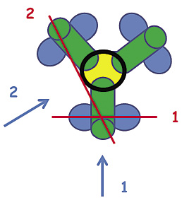
Figure 1. Schematic elements of a touch-trigger probe, looking down the stylus axis from the back of the probe.
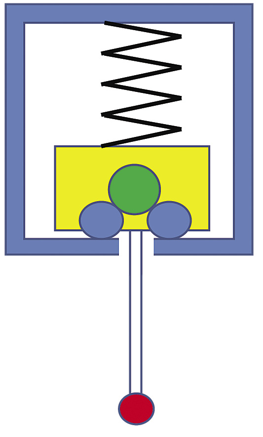
Figure 2. Schematic elements of a touch-trigger probe, including the stylus (white), tip (red), block (yellow), end of one of the cylinders (green), two supporting spheres (blue) and preloading spring (black).
Figures 1 and 2 schematically demonstrate the typical internal structure of a touch-trigger probe. In Figure 1, the view is from the back of the probe, down the probe shaft, or stylus, toward the tip. The probe stylus is attached to the block in the middle (yellow), but is not visible in this view. The block, in turn, is attached to three cylinders (green). The probe body consists of the stylus, block and cylinders and is separate from the probe housing. The three cylinders rest on six spheres (blue) and are preloaded against the spheres by a spring (black circle).
Figure 2 shows the probe from the side, including the probe stylus (white), probe tip (red), block (yellow), end of one of the cylinders (green), two of the supporting spheres (blue) and preloading spring (black). In this view, the probe housing (appearing as a blue rectangle) would be mounted in the spindle.
The cylinders and spheres are in the path of an electrical circuit. When the probebody is seated against the spheres and held in place by the spring, an electrical connection is made and the resistance of the circuit is low. When the probe tip contacts the workpiece, the force at the tip causes the probe body to move. When one of the cylinders loses contact with the spheres, resistance increases and the probe triggers. In practice, the resistance increases proportional to force, and the probe is set to trigger when a resistance threshold is reached. This design has several key advantages:
Review the print ads from this magazine to continue
This quick advertiser review unlocks the rest of the article and keeps the full-screen reader focused on the ads instead of the page chrome.
Advertisers included in this article experience
Print placements connected to this article
Nlgrades Stellramapps
Next Level
New Look Make a Performance Statement Stellram introduces a new line of NL Turning Grades that have the look and feel of fine jewelry. Behind the sophisticated look, however, is the Next Level of industry-leading advanced technology. Five new NL Turning Grades that increase metal removal rates, improve surface finish and provide up to a.
Next Level New Look Make a Performance Statement Stellram introduces a new line of NL Turning Grades that have the look and feel of fine jewelry. Behind the sophisticated look, however, is the Next Level of industry-leading advanced technology. Five new NL Turning Grades that increase metal removal rates, improve surface finish and provide up to a 30% longer tool life.
Visit Nlgrades Stellramapps View this placement in the issue recordPrint ads from this magazine
New Look Make a Performance Statement Stellram introduces a new line of NL Turning Grades that have the look and feel of fine jewelry. Behind the sophisticated look, however, is the Next Level of industry-leading advanced technology. Five new NL Turning Grades that increase metal removal rates, improve surface finish and provide up to a.
Next Level New Look Make a Performance Statement Stellram introduces a new line of NL Turning Grades that have the look and feel of fine jewelry. Behind the sophisticated look, however, is the Next Level of industry-leading advanced technology. Five new NL Turning Grades that increase metal removal rates, improve surface finish and provide up to a 30% longer tool life.
Continue reading
December 2013
1. When the probe body is seated, it is kinematically mounted. This means the probe body is restrained against translation or rotation in any direction until the spring force is overcome. The probe body can be accurately and repeatably seated in this position.
2. The probe can strongly contact or collide with the workpiece without causing or experiencing damage. That is, the probe can travel well past the initial contact, increasing the distance between the cylinders and spheres, without damaging the probe or workpiece.
3. The probe stylus can be changed for reach and access purposes, and the probe still functions. The styli can vary in length, diameter and material, and even incorporate right-angle turns.
4. The trigger threshold can be adjusted to trigger at a lighter or more forceful contact level.
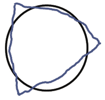
Figure 3. An example of a probe lobing error, where the probe shows a triangular shape when measuring a perfectly circular object.
While on-machine probing is useful, some errors are inherent to the process. One is probe lobing, which arises from the mechanical structure of the probe. Depending on the direction of contact between the workpiece and the probe tip, the force required to overcome the spring changes.
If the contact acts in the direction marked 1 in Figure 1, the probe body pivots around the red line marked 1. If the contact is in the direction marked 2, the probe body pivots around the red line marked 2. These two lines are different distances from the action line of the spring and require different forces to reach the trigger threshold. The result is that even when measuring a perfectly circular object, the probe shows a triangular shape (Figure 3).
High trigger forces and long styli increase the error by possibly 0.001 ” or more. While measurement of a known artifact can allow characterization of the possible magnitude of a lobing error, it is usually difficult or impossible to compensate for the error. This is because the direction of contact and orientation of the probe in the spindle are generally not known. CTE
About the Author: Dr. Scott Smith is a professor and chair of the Department of Mechanical Engineering at the William States Lee College of Engineering, University of North Carolina at Charlotte, specializing in machine tool structural dynamics. Contact him via e-mail at kssmith@ uncc.edu.
Related




Subscribers can use MFGAxis notes, saves and discussion tools with their innoNET account.


