

Shop develops self-leveling clamp: General Industry Coverage
The Workholding column in the April 2013 issue of Cutting Tool Engineering magazine shares the story of a shop facing a machining requirement for finishing small die-cast aluminum engine covers.
The goal of every workholding setup is the same: holding and supporting the part so it doesn’t move during machining. This is especially challenging when machining thin-wall, near-flat, die-cast components, which can easily distort under clamping forces that would be relatively small for parts with larger dimensions.
Die-cast aluminum automotive parts are being used more frequently because they help lighten the weight of vehicles without sacrificing strength. In many cases, they’re cast into near-net shapes, which minimizes machining and improves productivity.
Courtesy of Jesel
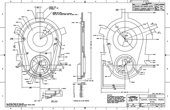
A blueprint of the die-cast aluminum engine cover showing the five clamping points.
Jesel Inc., Lakewood, N.J., a valve-train components manufacturer, had a machining requirement for finishing small die-cast aluminum engine covers. Due to the thinness of the casting, 0.150 ” to 0.250 ” between machine sides, and a 0.005 ” parallel flatness requirement, a standard fixed-point fixture clamp could not effectively hold the part.
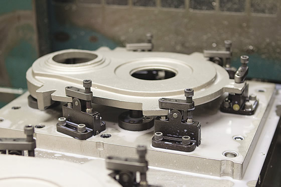
Fortunately, the components were cast with clamp pads (some die-cast aluminum parts no longer include them in the die-cast component to minimize weight). As a result, Jesel was able to develop its own self-compensating, or self-leveling, clamp to attach to those pads. The self-leveling feature, which moves the clamp in both directions until both sides of the clamp contact the surface, allows for casting thickness variation.
This clamping allows for the use of more clamps than just the ones used at the three primary point locators because the self-leveling design does not force the part out of its position. As a result, even with the added force from additional clamps, the part is less likely to distort in machining.
The self-leveling clamp for this particular application is approximately 2 “×3 “×3 “. It is basically a mounting block with an internal, dual-acting piston, a clamp screw on one side and a clamp button on the other.
“It will clamp both sides of any feature within its range of about 0.100 “,” said Ray Frattone, director of manufacturing for Jesel. “It solves the problem of having to use separate, adjustable work supports in addition to the clamp because it adjusts to the casting and does not force it up or down from the three primary point locators. These work supports typically require skill and time to execute properly. With our clamp, tightening one screw is all that is required.”
All areas of the casting shown in the photo on page 31 require machining. The casting is first located on its three primary tooling points and then clamped on the tabs in five places (the three primary point locators and two additional clamp pads) by tightening five screws with a ¼ “-drive air driver.
Review the print ads from this magazine to continue
This quick advertiser review unlocks the rest of the article and keeps the full-screen reader focused on the ads instead of the page chrome.
Advertisers included in this article experience
Print placements connected to this article
Rego FIX
VISIT US AT PMTS
IN BOOTH #238 CONSIDER THIS: 72% MORE TOOL LIFE powRgrip® TOOLHOLDING COLLET SYSTEM WATCH HOW powRgrip® CAN IMPROVE YOUR BOTTOM LINE. SWISS TYPE Swiss Precision SWISS PRECISION TOOLS.
VISIT US AT PMTS IN BOOTH #238 CONSIDER THIS: 72% MORE TOOL LIFE powRgrip® TOOLHOLDING COLLET SYSTEM WATCH HOW powRgrip® CAN IMPROVE YOUR BOTTOM LINE. SWISS TYPE ER COLLET SYSTEM CYLINDRICAL HOLDERS WWW.REGO-FIX.NET/POWRGRIPVIDEO
Visit Rego FIX View this placement in the issue recordPrint ads from this magazine
IN BOOTH #238 CONSIDER THIS: 72% MORE TOOL LIFE powRgrip® TOOLHOLDING COLLET SYSTEM WATCH HOW powRgrip® CAN IMPROVE YOUR BOTTOM LINE. SWISS TYPE Swiss Precision SWISS PRECISION TOOLS.
VISIT US AT PMTS IN BOOTH #238 CONSIDER THIS: 72% MORE TOOL LIFE powRgrip® TOOLHOLDING COLLET SYSTEM WATCH HOW powRgrip® CAN IMPROVE YOUR BOTTOM LINE. SWISS TYPE ER COLLET SYSTEM CYLINDRICAL HOLDERS WWW.REGO-FIX.NET/POWRGRIPVIDEO
Continue reading
April 2013
“The part is not distorted by this action,” Frattone said. “We can now machine the top of the part complete and machine level two and level five on the opposite side using a back flycutter with two inserts and going through the two large bores.”
For the opposite side of the part, Jesel locates on the two large bores and clamps the part on levels two and five while supporting the opposite side in several areas. While machining the second side, the five clamping tabs are removed, completing the machining.
“Before we devised this clamp, we tried without success to machine this part flat,” he said.
The clamp can also be used for other applications, such as a rectangular casting that looks like a shoebox with no bottom. The four walls are each about ¼ ” thick. “We can grab the walls with as many clamps as necessary, with the casting located by the conventional six tooling points,” Frattone said.
Courtesy of Jesel
Jesel’s machining setup for a die-cast aluminum engine cover with self-leveling clamps devised by the shop in place.
Another possible application for the clamp would be a small gasoline engine cylinder head that could be located on six points and clamped on the cooling fins on the opposite side of the machined area. “The possibilities are limited only by your imagination,” Frattone enthused.
Those possibilities could include larger housings, such as oil pans, flange hubs, pump covers and gear housings that can take advantage of the additional support without fear of the clamps bending the part.
This ingenious little clamp is an excellent example of the innovation and the imagination required to solve workholding problems and create good parts in the time requested. CTE
About the Author: Joe Mason is sales cost estimator for Schwartz Industries Inc., Warren, Mich. He has worked in the metalworking industry since 1978. Contact him at cncgcode@earthlink.net.
Related



Subscribers can use MFGAxis notes, saves and discussion tools with their innoNET account.


