

Becoming familiar with CAM: Turning Performance
Shop Operations column looks at the benefits of becoming familiar with CAM software.
When our computer system crashed and was down for a few days, we were forced to write our programs manually to keep the wheels of industry turning. That was an eye-opener. A job that would normally take minutes to program took more than 10 times as long, if we could do it at all. And when a program was finally written manually, there was little confidence in it—for good reason—because it was usually loaded with mistakes.
The CAM system we use is CAMWorks, from Geometric. We chose the software some years ago because it was the only CAM package at that time that could be integrated with Geometric’s SolidWorks on the modeling side. It has worked well for us.
One of the advantages of having the CAM software integrated with SolidWorks is that when you launch the SolidWorks application, the CAM application is immediately available for use.
Another benefit is that when working with a SolidWorks model, the toolpaths applied to the model with CAMWorks are saved in the SolidWorks file. It’s a compact, user-friendly arrangement.
Before I discuss how using CAM software makes my life easier, I’d like to point out that there are still jobs I feel more comfortable doing on manual, or conventional, machines. Jobs where the setup is skewed in some way come to mind. Our shop doesn’t have a 5-axis machine, so we have to tilt parts, which makes it difficult to pick a starting point.
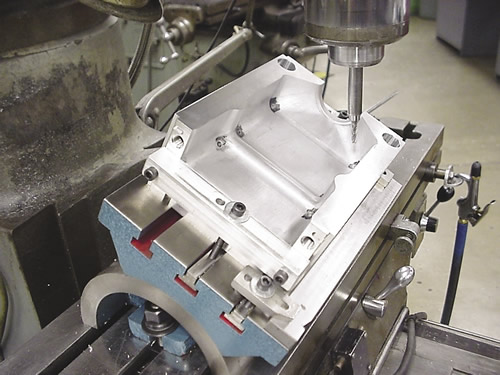
For example, we ran one job on a CNC mill in which we had to put vent pinholes in about a dozen mold cavities. The cavities had to be tilted to get the holes in at the correct angle. We mounted a tooling ball on the cavities at a known location to get a starting point. The holes had to be close in diameter and precise in depth for the vent pins to press into them. The entire operation was risky.
Review the print ads from this magazine to continue
This quick advertiser review unlocks the rest of the article and keeps the full-screen reader focused on the ads instead of the page chrome.
Advertisers included in this article experience
Print placements connected to this article
Fax +1 817 258 3221, [email protected]
ISCAR's Winning Edge
Drilling Innovations Excellent Cylindricity and Superb Surface Finish! Self ISCAR METALS INC
ISCAR's Winning Edge Drilling Innovations Excellent Cylindricity and Superb Surface Finish! Self ISCAR METALS INC. Tel +1 817 258 3200, Tech Tel 1-877-BY-ISCAR Fax +1 817 258 3221, [email protected] www.iscarmetals.com
Visit Fax +1 817 258 3221, [email protected] View this placement in the issue recordAmamcotool
COM E
SHAKE TH E HAN DS THAT MAKE T H E TOOLS ! Visit us at IMTS, Booth W-1573 Stop by the AMAMCO booth at IMTS, to meet the people who make the tools to build the aircraft that defend the nation. Aerospace and other demanding industries have looked to AMAMCO for decades for carbide tooling for their very special applications and materials
COM E SHAKE TH E HAN DS THAT MAKE T H E TOOLS ! Visit us at IMTS, Booth W-1573 Stop by the AMAMCO booth at IMTS, to meet the people who make the tools to build the aircraft that defend the nation. Aerospace and other demanding industries have looked
Visit Amamcotool View this placement in the issue recordPrint ads from this magazine
Drilling Innovations Excellent Cylindricity and Superb Surface Finish! Self ISCAR METALS INC
ISCAR's Winning Edge Drilling Innovations Excellent Cylindricity and Superb Surface Finish! Self ISCAR METALS INC. Tel +1 817 258 3200, Tech Tel 1-877-BY-ISCAR Fax +1 817 258 3221, [email protected] www.iscarmetals.com
Continue reading
September 2016
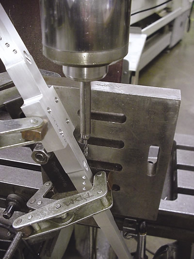 The next time the job came up, I chose a conventional milling machining to install the vent pinholes. What a relief! It took half the time to install them compared to using the CNC machine—and with a lot less stress. The mold cavities were, of course, machined on a 3-axis CNC machine.
Another job I chose to run on a conventional milling machine is shown on page 38. Again, the holes had to be machined at a fairly extreme angle. The base part, however, was machined on a CNC mill.
In many cases, CNC machines simply are not substitutes for competent machinists.
When using CAM software, the first thing you need is a computer model of a part. The model allows you to apply cutter sizes and other machining parameters such as feeds, speeds and DOC to simulate cutting the model on a computer. Using CAM, you can get a good-but-not-perfect idea on the computer about how the process will run before putting the job on a machine.
CAM applications generate the G code that tells the spindle where to move and how fast to cut using a particular cutting tool. However, generating G code is almost an afterthought because it takes no thinking on your part. Once you’ve chosen toolpaths and input machining parameters, the G code is just a few clicks away.
Automatic programming utilities can be handy, but you’ll still fine-tune the program to get things to run the way you want. I tend to shy away from these utilities at the expense of taking more time initially. I prefer choosing the types and sizes of the cutters myself.
When vendors demonstrate CAM software at trade shows, they can program just about anything in seemingly no time at all, and the part will be cut beautifully on the computer. But you can bet vendors that demonstrate machines actually cutting metal have spent a lot of time fine-tuning their programs.
Related




Subscribers can use MFGAxis notes, saves and discussion tools with their innoNET account.


