

Reversal techniques in measurement: General Industry Coverage
The Machine Technology column in the August 2014 issue of Cutting Tool Engineering magazine reviews the use of the reversal technique in machine measurement.
The accuracy with which a machine tool can produce parts is determined in part by the accuracy of the motions of the machine axes. The motion in a given coordinate direction should be straight, and the motion in other coordinate directions should typically be perpendicular to that. Motion straightness and perpendicularity is checked when a machine is built, rechecked when installed and should be periodically rechecked throughout its operating life.
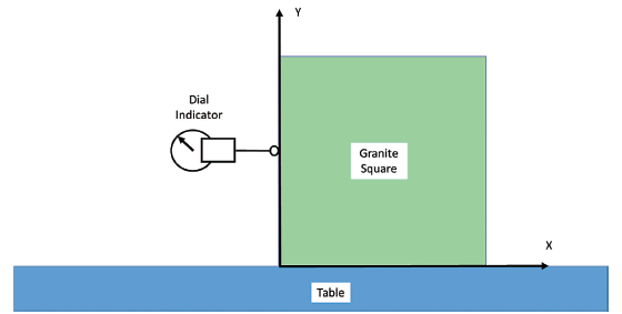
A granite or cast iron metrology square can be used to measure the squareness of the X and Y axes of a machine tool (Figure 1). A common size for a granite square is 12 “×12 “×3 ” (304.8mm × 304.8mm × 76.2mm), and it would weigh a little less than 50 lbs. Larger squares exist, but are difficult for a person to lift without assistance. Typical flatness tolerances for surfaces of such squares are one part in 120,000 to one part in 250,000.
All images courtesy S. Smith
Figure 1. Measuring the squareness of the X and Y motions using a precision square.
If the top of a table is flat, and that surface is aligned with the X motion of the machine, it is easy to see how the square could be used to measure the squareness of the axis motions. A dial indicator is attached to the moving element and brought into contact with the vertical edge of the square. As the Y-axis is moved, the dial indicator reading at various positions shows X-axis errors in the Y-axis motion.
Squareness is the angle between the X motion and the Y motion, but neither motion is perfect. The sides of the square are perpendicular to a high tolerance. The X side of the square is lined up with the X motion, and a dial indicator is used to measure the distance to the Y side of the square as the Y-axis is moved. The result is not a straight line, but a wavy line, because the motion is not perfect. The Y motion is interpreted as the best fit straight line through the data measured with the dial indicator. The angle between that line and the X motion is the squareness.
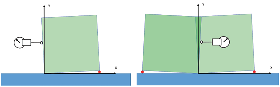
However, this simple measurement idea is mixed with several possible errors. For example, the square may not be sitting flat on a flat surface. Figure 2 shows a small piece of debris between the square and table, tilting the square to one side. If the vertical edge was measured in this case, it is not possible to tell whether the X and Y motions of the machine are not square to each other or whether the granite square is tilted. Perfect Y motion—perfectly perpendicular to the perfect X surface—would still look like an error in squareness, which is greatly exaggerated for clarity in the figure.
Review the print ads from this magazine to continue
This quick advertiser review unlocks the rest of the article and keeps the full-screen reader focused on the ads instead of the page chrome.
Advertisers included in this article experience
Print placements connected to this article
results that are always a cut above. www.hornusa.com
Parting-off performance at its peak
At HORN, we take a systematic approach to parting off, from the holder – offered with a range of shanks – to the insert. Groove widths from 0.5 mm (.02099) to 16 mm (.63099) and groove depths up to 65 mm (2.55999). This is how we ensure that you can machine your work pieces with speed, precision, feed rates when the engagement times are long. Additionally, our patented solutions allow the insert.
Parting-off performance at its peak At HORN, we take a systematic approach to parting off, from the holder – offered with a range of shanks – to the insert. Groove widths from 0.5 mm (.02099) to 16 mm (.63099) and groove depths up to 65 mm (2.55999). This is how we ensure that you can machine your work pieces with speed, precision, and efficiency. We provide excellent chip control, secure clamping, and straight cuts even with high www.hornusa.com feed rates when the engagement times are long. Additionally, our patented solutions allow the insert to be changed safely and without damaging the cutting material. Team up with a technology leader for results that are always a cut above. www.hornusa.com H O R N – E X C E L L ENCE IN TECHNOLOGY GROOVING PA R T I N G O F F GROOVE MILLING BROACHING PROFILE MILLING DRILLING REAMING
Visit results that are always a cut above. www.hornusa.com View this placement in the issue recordPrint ads from this magazine
At HORN, we take a systematic approach to parting off, from the holder – offered with a range of shanks – to the insert. Groove widths from 0.5 mm (.02099) to 16 mm (.63099) and groove depths up to 65 mm (2.55999). This is how we ensure that you can machine your work pieces with speed, precision, feed rates when the engagement times are long. Additionally, our patented solutions allow the insert.
Parting-off performance at its peak At HORN, we take a systematic approach to parting off, from the holder – offered with a range of shanks – to the insert. Groove widths from 0.5 mm (.02099) to 16 mm (.63099) and groove depths up to 65 mm (2.55999). This is how we ensure that you can machine your work pieces with speed, precision, and efficiency. We provide excellent chip control, secure clamping, and straight cuts even with high www.hornusa.com feed rates when the engagement times are long. Additionally, our patented solutions allow the insert to be changed safely and without damaging the cutting material. Team up with a technology leader for results that are always a cut above. www.hornusa.com H O R N – E X C E L L ENCE IN TECHNOLOGY GROOVING PA R T I N G O F F GROOVE MILLING BROACHING PROFILE MILLING DRILLING REAMING
Continue reading
August 2014
Figure 2 (left). An error occurs when measuring squareness because of a poorly mounted square. Figure 3 (right). Reversing the square and averaging the measurement eliminates the error caused by poor square mounting.
To remove this error from the measurement, use a clever trick called a “reversal.” The idea is to make two measurements of the same thing, but change the sign on the error you do not want to include. When the two measurements are added together, the unwanted part cancels out, and the wanted part is doubled. Therefore, the correct measurement is the average of the two measurements (one normal and one reversed).
Figure 3 on the opposite page shows this idea. In this case, the original measurement was made on the tilted square as in Figure 2. Then, the square is rotated about the measurement axis, and the dial indicator is turned around so it measures the same surface of the square again. It is important that the measurement be made along the same line as before and with the same side of the square.
In Figure 3, the superimposed errors appear in dark green, and the average of the two measurements splits the error. The tilt of the square is removed from the measurement of the squareness of the axis motions. In a similar way, this reversal technique removes any error in the squareness of the precision square or errors in the straightness of the square edge.
Other similar techniques can show whether a machine is level. Reversing a level, such as one with a bubble in a tube of fluid, 180° around its vertical axis removes the error in the alignment of the edge of the level with the machine element. You might have seen brick layers checking the level of a line of bricks on a wall by reversing their levels for this same reason.
Another related reversal technique checks the straightness of an axis motion, comparing it to a straight edge. Such measurement would have been needed to establish that the table surface was aligned with the X motion of the machine in the figures. (We just assumed the flat table top was aligned with the X motion.)
Metrology professionals frequently perform reversal techniques for many applications, and the common theme is that the reversal changes the sign of the error, but not the sign of the intended measurement. CTE
About the Author: Dr. Scott Smith is a professor and chair of the Department of Mechanical Engineering at the William States Lee College of Engineering, University of North Carolina at Charlotte, specializing in machine tool structural dynamics. Contact him via e-mail at kssmith@uncc.edu.
Related




Subscribers can use MFGAxis notes, saves and discussion tools with their innoNET account.


