

Turning in a New Design
Here’s how a new part design became the “hub” of future victory for students working on the Formula SAE car project at Lafayette College in Easton, Pennsylvania. The year was 2013 and our Formula SAE car team had just returned from a successful run at their competition, albeit with some scorching critiques from the design judges.
Here’s how a new part design became the “hub” of future victory for students working on the Formula SAE car project at Lafayette College in Easton, Pennsylvania.
The year was 2013 and our Formula SAE car team had just returned from a successful run at their competition, albeit with some scorching critiques from the design judges. They really hammered us on the wheel assemblies, and the laundry list of potential failure points on them. Just about every single point where the wheel packages (wheel hubs, brakes, upright bearing housings, steering and suspension pickup points) interacted with something else, they had scathing feedback. We pushed the car back into the garage and licked our proverbial wounds, and then discussed what we’d do differently.
As is our history, the team was all college seniors, and they went on to graduate and start their careers, leaving the car to the next batch of incoming seniors. They did, however, leave behind a wish list of suggestions to my incoming team. (That list found its way to the recycle bin.)
Fast forward to the Fall semester of 2014. I met my new team assembled in the garage to pick up where my last team left off. This was a dream team of designers, drivers, gearheads and marketing gurus! Their elected leader for this new team was a man of so few words that, if he did speak, the words were either of wisdom or frustration, and everyone in the room listened. This team redesigned everything from the brake rotors and motor mounts to the cockpit and motor box, as well as everything in between. They managed to do all that in record time, something that has rarely happened in our history.
This brings us to today’s focus, turning out new wheel hubs. By new, I mean they are an original design and were completely machined from bar stock instead of being hobbled together from butchered Volkswagen Rabbit drivetrains.
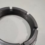
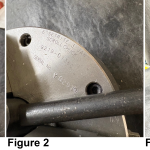
Figures 1 and 2 show the outside features of the parts as turned. This view is identical for all six pieces. I made the two for the front, the two for the rear, and a spare of each to pack in the toolbox in case the worst happened at the track.
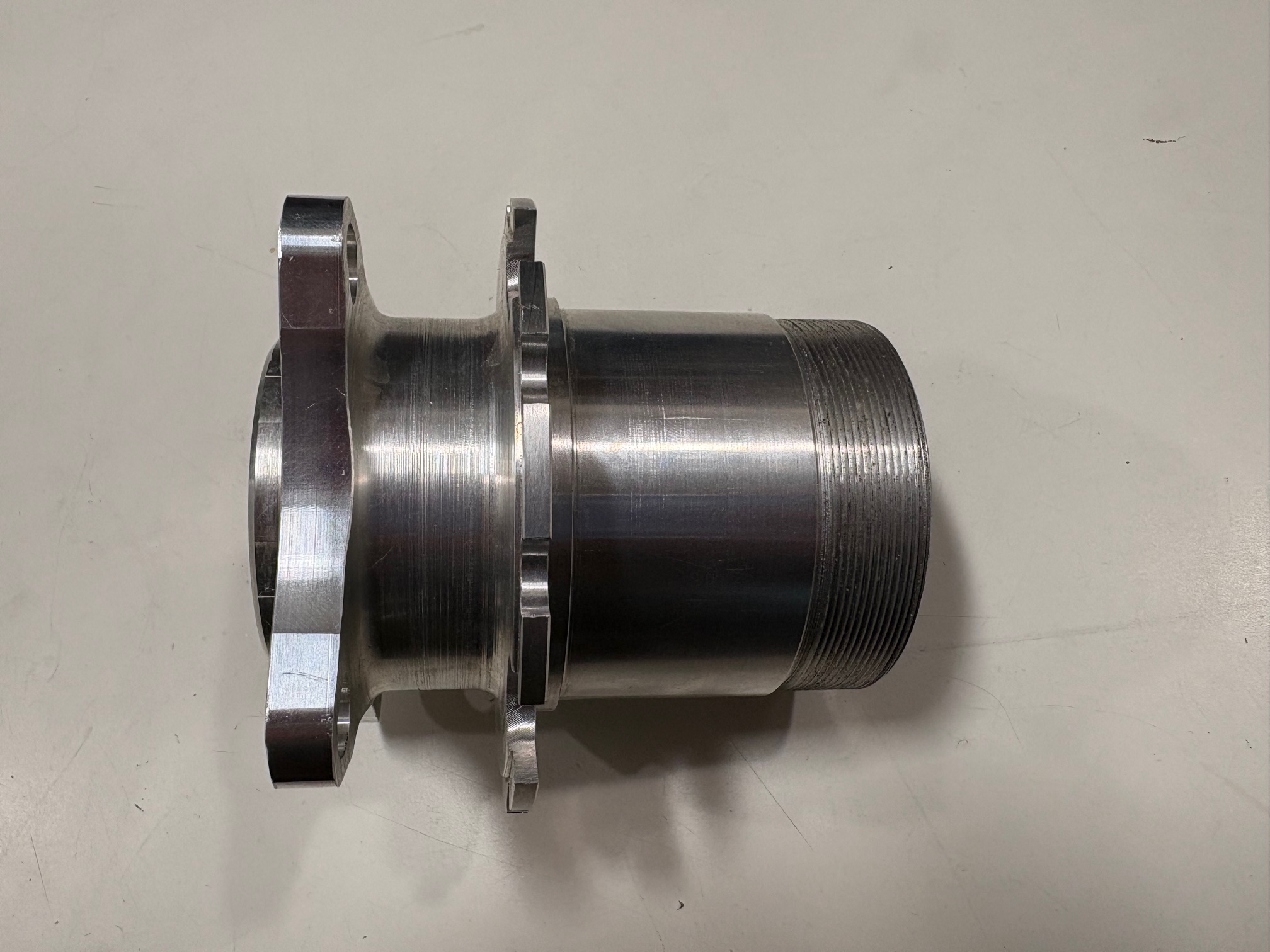
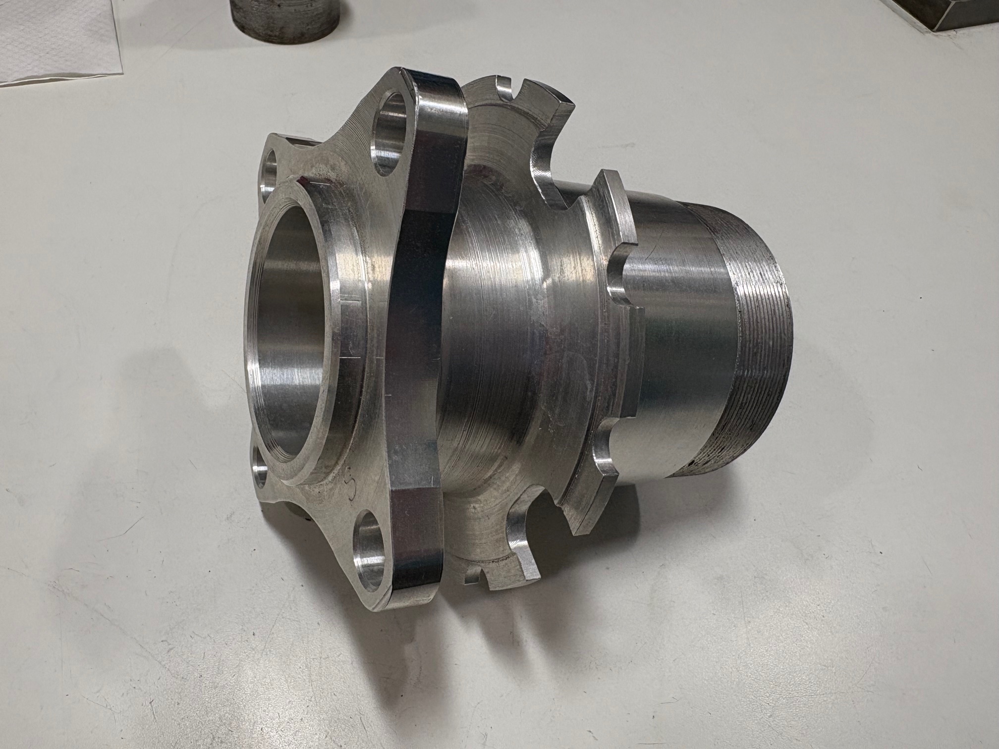
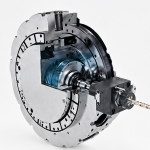
This new design embodied the principle of “monolithic integration” or making a single part that performs many jobs at the same time. Instead of bolting flimsy rings of steel to a flange for brake rotors, which in turn was bolted to another part that became the hat/hub/brake rotor, this hub integrated the flanges with the bearing diameter, pre-loading threads, wheel lug flange and the half-shaft input. This single part performed five separate operations all at the same time!
While it may sound wasteful to take a large chunk of stock, in this case a 5" diameter bar saw cut to roughly 6" in length, this method saves the added hardware and weight of redundant parts. Despite the pile of chips and shavings from cutting a half dozen of these things, you must remember two important points:
First, I work in a prototyping shop, and these are acceptable losses in the quest for a successful design.
Second, these parts still retained a substantial amount of the material while weighing in at a fraction of what their predecessors did.
For this part, I started the machining with use of the factory hard jaws on the three-jaw chuck, gripping on the part with a little extra bite while sticking enough of the material out to turn most of the features in one setup before needing to reverse the part to finish it.
As a result of the increased precision and repeatability, I chose to machine these parts in our CNC lathe. I programmed the machine to face the part, turn the OD of the threaded area, the bearing diameter, the shoulders, and the OD for the brake rotor mounting flange. I also programmed the machine to turn the brake rotor flange back a bit past the desired width so I could clean up the back surface in the finishing setup.
Review the print ads from this magazine to continue
This quick advertiser review unlocks the rest of the article and keeps the full-screen reader focused on the ads instead of the page chrome.
Advertisers included in this article experience
Print placements connected to this article
LMT Onsrud Cutter LP
LMT Onsrud Cutter LP print ad
Print ad listed on page 11 of the June/July 2026 issue.
Visit LMT Onsrud Cutter LP View this placement in the issue recordGreenleaf Corp.
Greenleaf Corp. print ad
Print ad listed on page 12 of the June/July 2026 issue.
View this placement in the issue recordGreenleaf Corp.
Greenleaf Corp. print ad
Print ad listed on page 13 of the June/July 2026 issue.
Visit Greenleaf Corp. View this placement in the issue recordPrint ads from this magazine
Print ad listed on page 11 of the June/July 2026 issue.
Continue reading
June/July 2026
Next, I had the machine switch tools and put a small undercut at the end of the threaded shank, so the threading tool had a place to run off.
After that was the threading operation, a custom thread that I will discuss in more depth in another column. The print called for a 2.875"-20 unified thread custom fit to a mating lock nut. I simply touched off the threading tool in my initial setup, told the machine the diameter of the thread and the distance between the threads and the machine spun away, with two additional spring passes to ensure it cleaned up properly.
Our machine is a conversational-type CNC. You simply input your start and end dimensions, and the control calculates tool nose offset and triangulations for you. Great for small lot work, or for those who aren’t savvy with G- and M-Code programming, yet want some CNC capabilities. Being able to put in the diameter, distance between threads, desired spindle speeds and thread lengths with mere numerical decimal values and getting a finished part at the end of the cycle is a big selling point for this type of machine. Since I was using these parts as the thread gauge for the lock nuts, I checked the threads with a pitch gauge and called it good.
The last operation in this setup for the rear wheels is the pilot drill for the half-shaft pocket and grease fitting tap drill. Using the tailstock, I stepped up drill sizes until I reached the diameter of the round-bottom pocket. Then, using a drill that I ground to have a rounded cutting surface instead of the standard drill point tip, I sank that drill to the desired depth. Lastly, I sank the tap drill for a 3/8"-24 UNF thread through the center deep enough that it would open out in the opposing counterbore in the second side. For the front wheel hubs, since they served no power transmission purpose, they were simply drilled and bored out to leave a 0.250" thick wall to the smallest outer diameter feature to give the hubs a high strength-to-weight ratio.
For finishing these parts on the second side, I did not want to use the factory hard jaws on the chuck because I would be gripping the parts on a finished diameter, the bearing surface. I needed a set of custom soft jaws bored out to the diameter of the bearing surface. (To see how we tackled the making of soft jaws for our lathes, see my earlier article “Eccentricity Rings True” in the January 2025 issue.)
On the advice of a coworker who spent many years doing finish and repair work by making soft jaws, I bored the jaws to about 0.002" smaller than the desired diameter, ensuring a strong grip on these hubs as they were being finished.
After taking a skim cut on both the face and the OD of the unfinished side, and setting the tools to it, I programmed the remaining features and let the machine turn all that excess stock into chips. This included the turning of the shoulder for the wheel’s center hub to rest on, the OD for the stud flange, and the undercut between that and the brake rotor flange. For the front wheel hubs, the same bore was cut and match turned as it was on the first side. For the rears, a weight reducing counterbore was sunk in, leaving a wall for the half-shaft to press against and capture the grease for lubricating the half-shaft ends.
With all the turning completed at this point, all six parts were sent over to our CNC mill to get the holes for the studs and the cutouts for the floating brake rotor pins (see Figure 3). The rears received the three-lobe pockets for the tripod rollers to ride in, as well as the three threaded holes used to hold down the collar that captures it all together (see Figure 4).
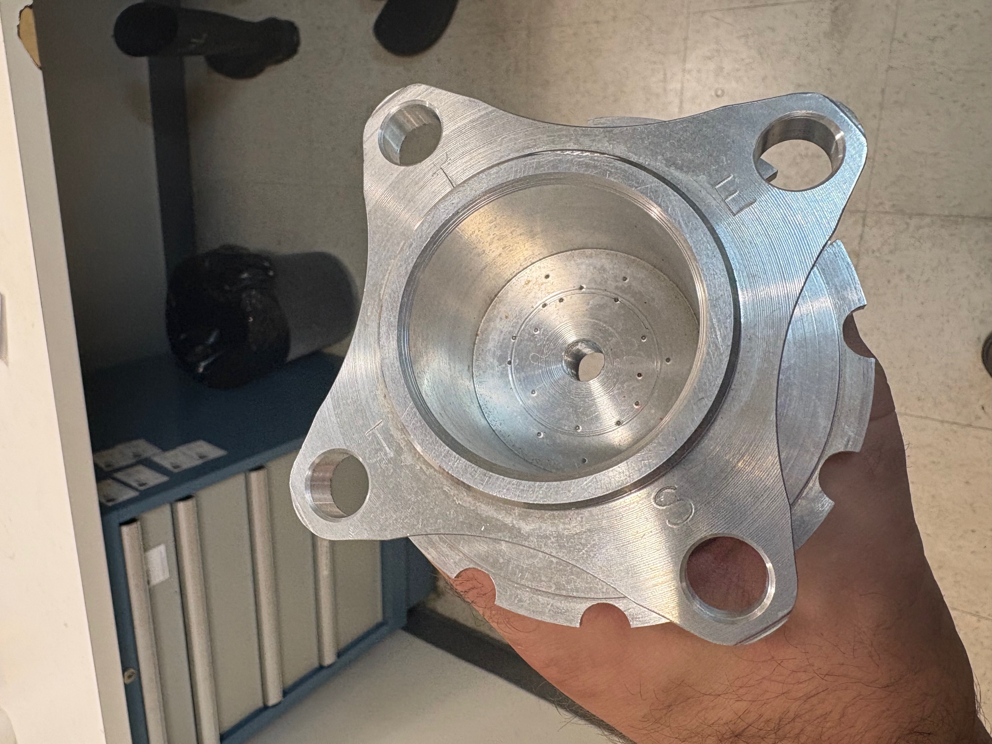
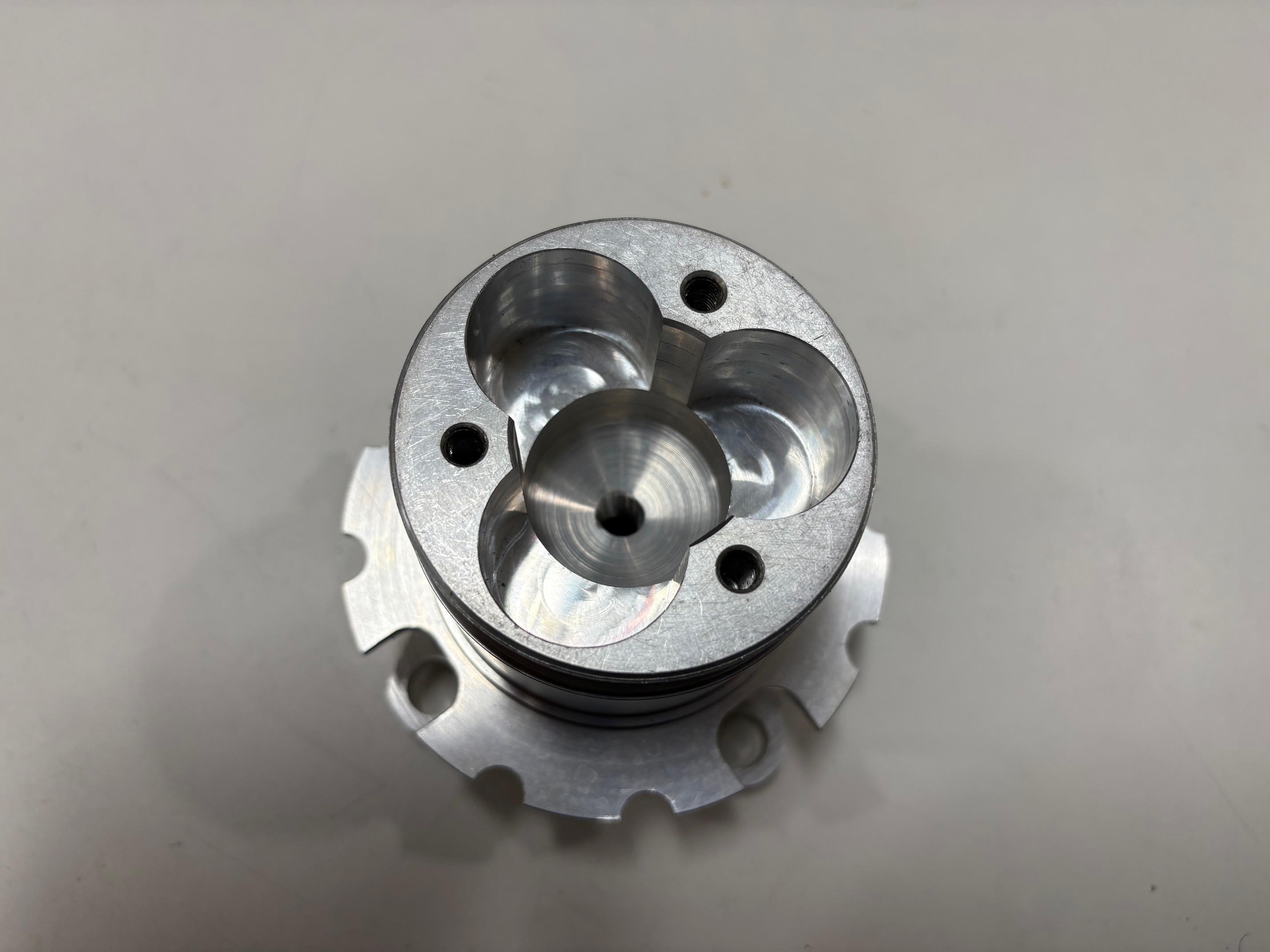
One thing I was able to do while programming at the control — and something I reinforce when training other employees in the use of the machine — was the practice of burying the insert’s tool nose radius until I was doing the light finishing passes. This allows the chip breakers to do their job, preventing those ghastly bird nests that can show up when stringy chips and a spinning lathe chuck meet. Carbide inserts have come a long way since I started in my career; most of them are able to outperform whatever speeds and feeds our machines are even capable of achieving! For most of you reading this, the mantra of “money is only made when chips are flying” is doctrine. Make that happen!
A special thank you goes out to Mechanical Engineering Professor Scott Hummel, Ph.D., for providing the wheel hub sample for photographs.
Related

Subscribers can use MFGAxis notes, saves and discussion tools with their innoNET account.


