Building bridges
Building bridges
Quality Industries Inc. has always been quick to react to new trends by reinventing itself.

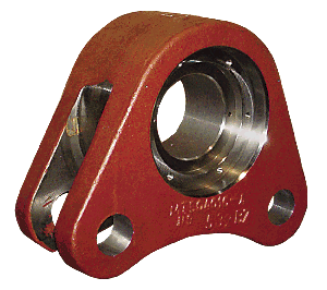
Quality Industries fabricated custom tooling to efficiently machine this approximately 200-lb. heavy equipment component made of steel.
Quality Industries Inc. has always been quick to react to new trends by reinventing itself, according to Jim Kaplan, company vice president. With his brother and company President Jerry Kap- lan, Jim runs the job shop their grandfather founded in Cleveland in 1946. The shop has continually evolved in response to changes in its customers and marketplace. Over the years, it has produced parts for a range of familiar industries, as well as "a lot of oddball stuff," Jim said.
Currently, a maker of demolition equipment contracts the machine shop to make a component called a bridge. The part looks like a giant bushing with two pairs of protruding flanges, or "ears." In use, two bridges connect demolition shears, or claws, to the boom on a piece of heavy equipment.
Quality Industries makes the bridge in three sizes, with basic finished dimensions from 12 "×17 "×7 " to 15 "×20 "×9 " and weights from 140 to 260 lbs. The parts are machined from near-shape castings of heat-treated 4340 steel (32 to 37 HRC). Part runs typically consist of 10 pieces, or five matching pairs.
To create concentric bores and counterbores in the part, initial operations take place on an Acra CST 50200 CNC lathe. The casting's weight and semi-triangular shape make it a challenge to chuck and spin it. The solution is bolt-on counterweights. For a midsize bridge, for example, the counterweight is about 60 lbs., an amount determined by experimentation. The weight balances the part and enables it to spin smoothly.
After indicating a casting to put it on center in the lathe, the shop faces the part's front with a Tungaloy CNMG 643 insert run at 200 sfm, a 0.100 " WOC and about a 0.025-ipr feed rate. Jim Kap-lan said he runs the insert "somewhat slow" to lessen the tool-damaging effects of voids and hard spots in castings.
Next, to create the part's central bore, Quality Industries uses a quick-change boring system that was designed and fabricated in-house. The tooling consists of a 2½ "-dia. bar with bolt-on heads to hold standard ¾ "-square-shank turning tools. "I have three or four different heads with tools in them," Kaplan said. "That way, when changing tools, I don't have to change the bar itself."
The first boring operation opens a 5.499 "- to 5.500 "-dia. hole about 7 " deep through the part's center, using a TMX coated TPG 322 insert running at about 125 sfm and a 0.01-ipr feed. Then another toolholder and a mechanism permits fine adjust…" title="Single- or multiple-point precision tool used to bring an existing hole within dimensional tolerance. The head attaches to a standard toolholder and a mechanism permits fine adjust…" aria-label="Glossary: boring head">boring head with a WMNG trigon insert enlarges a 9.040 "- to 9.045 "-dia., 1⅜ "-deep counterbore at the front of the part.
Another head and tool change permits the shop to reach in and create a counterbore at the back of the part. The tool is moved into the part, and then the tool back bores towards the front, enlarging the 5.500 "-dia. hole to 7.410 " to 7.415 ". Part specifications require a distance of 4.375 " (±0.005 ") between the front and back counterbores. Therefore, after the initial roughing passes, the tool is backed out and measurements are taken. "I may still have 0.010 " left on the thickness," Kaplan said, "but I'd rather have the stock than not. I can go back in and remove it on a finish pass."
After ID boring is completed, the part stays on the lathe, which turns the OD between the ears to a diameter of 11.498 " to 11.500 ". The shop fabricated another custom toolholder for this operation. The holder is a steel extension with pockets to hold square-shank MWLNL and MWLNR toolholders for accepting trigon inserts. After the shoulder and part OD closest to the front counterbore is turned with one tool, Kaplan loads the extension with the opposite hand tool and finishes the rest of the OD, blending the cuts together. "I flip it back and forth, removing about ⅜ " of material per side," he said.
Casting variations sometimes require additional facing inside of the ears to achieve the 3.25 " width required between them. Kaplan said the surface finish requirement is generally 63 μin. Ra.
Lathe operations for the midsize bridge consume about 8 hours per part, after which it is moved to a Johnford VMC 1124 CNC vertical mill. There, the first set of operations involves opening a 9.48 "-dia. (±0.010 "), 1.25 "-deep counterbore on what was the part's back side when it was clamped in the lathe. To remove material quickly, the shop rough bores the ID with a Sandvik Coromant 2.0 "-dia. shell mill tooled with four ½ "-dia. button inserts, helically interpolating in 1/16 " steps at 600 rpm and 15 ipm.
Then a 2 "-dia., 5-flute, square-shoulder inserted shell mill removes scallops in the part wall left by the roughing cutter, leaving 0.010 " to 0.015 " stock for finishing. The mill's square shoulder also forms a 90° corner in the counterbore's bottom and establishes its depth.
After a 2-flute, 1.250 "-dia. indexable K-tool chamfering-tool/" data-glossary-id="142011" data-glossary-teaser="Cutter or wheel that creates a beveled edge on a tool or workpiece." title="Cutter or wheel that creates a beveled edge on a tool or workpiece." aria-label="Glossary: chamfering-tool/" data-glossary-id="142011" data-glossary-teaser="Cutter or wheel that creates a beveled edge on a tool or workpiece." title="Cutter or wheel that creates a beveled edge on a tool or workpiece." aria-label="Glossary: chamfering tool">chamfering tool">chamfering tool puts a 3/16 "×45° chamfer on the counterbore's outside edge, a solid-carbide endmill finishes the bore. Kaplan said he typically applies a Niagara or an OSG cutter, in whatever diameter between ⅝ " and 1 " is handy at the time.
Next, jobber-length HSS drills make 10 holes at the bottom of the 9.5 "-dia. counterbore. Eight of the holes are tapped to ½-13, and two are reamed to 0.376 " in diameter.
Describing drilling and boring holes in the part's protruding ears, Kaplan said, "That's where we make up some time." Previously, the 2⅝ "-finished-dia. holes in the ears on one side of the part were roughed with a drill/mill tool and bored to a rough size. Then, after the heavy part was turned and indicated back into place, the drill/mill and boring operations were repeated on the ears on the other side. At that point the holes were finish-bored inline. The process required "a lot of handling and a lot of time," Kaplan said. "It probably took us a couple of hours, per hole, to get it roughed in." Completing all the holes on one part took a day and a half to 2 days.
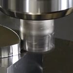
Kaplan said the local Sandvik Coromant representative suggested using a high-feed plunge mill to create the holes instead. "It has the reach to get through from one side and eliminate all the handling," Kaplan said. "Now we do it in one setup. We use a 1½ "-dia. plunge mill, running around 1,150 rpm. It helically interpolates, feeding down 0.040 " per pass at about 88 ipm. Each hole in an ear takes about 5 minutes."
After enlarging the holes, the shop bores them to a ±0.002 " tolerance with a Criterion or Command boring head. For one part, operations on the VMC consume a full day or a day and a half.
Final part operations consist of drilling cross-holes and grease holes on a Scharr-man horizontal boring mill. CTE
Image courtesy of Quality Industries. For more information about Quality Industries Inc., call (216) 961-5566.


