Optimizing Cutting Speeds
Optimizing Cutting Speeds
The man behind the Machining Doctor website offers a mathematical approach to refining speeds for precision, stability and tool life.
All suppliers of cutting tools offer cutting speed recommendations for their products. However, these suggestions are often very general and meant for nearideal conditions such as stable clamping, annealed materials and optimal carbide grade. Consequently, the recommendations may be excessively high in various situations, necessitating adjustments for your specific application. This article will show you how to make these adjustments effectively.
Another practical application of the tips in this article arises when you have a cutting speed that performs well under certain conditions, but one of the parameters, such as material hardness or stability, changes. While you can use speeds and feeds calculators, understanding the fundamental parameters that influence these calculations will lead you to make much more informed decisions.
The suggested cutting speeds for products are typically found in product boxes and catalogs, both in print and online. It is recommended to disregard the speed suggestions on the product packaging. This is because the information provided on product boxes usually relates only to the six primary ISO material groups, whereas catalogs offer a far more detailed classification.
Supplier catalogs often include numerous subgroups within each main group. However, there is a lack of standardization among different suppliers, each creating their own classification of material groups. A typical list may present around 40 to 100 subgroups.
It is essential to dedicate sufficient time to correctly classify your material based on the supplier of the cutting tool you intend to use before proceeding to the next stage. While this process can be time-consuming, it is crucial not to take shortcuts here.
Having established the most precise starting point, we can now advance to the next steps for refinement.
Alternatively, you may rely on your previous experience with similar materials to find a starting point and adjust it using the guidelines provided below.
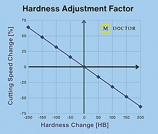
Hardness Adjustment Factor
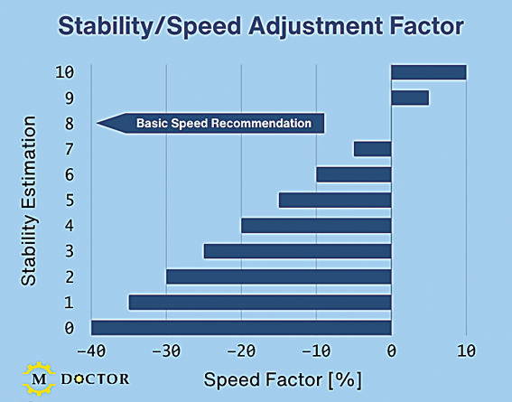
Stability/Speed Adjustment Factor
Mind the hardness
You might have experience with, or cutting speed suggestions for, a material in its annealed state, but it needs to undergo heat treatment before machining. A common use case is PH stainless steels or tool steel.
To modify the cutting speed, consult the "Hardness Adjustment Factor" chart. The X-axis represents the Brinell hardness difference between the material you're using and the one for which you have initial data. The Y-axis shows the necessary percentage adjustment to apply to the base cutting speed.
Stability is a crucial factor
The suitable speed for a machining operation is greatly influenced by the overall setup stability, which is a subjective parameter. This stability depends on the quality of clamping for both the workpiece and the cutting tool, along with the cutting tool's overhang. To evaluate the stability of your application, assign a score from 0 to 10, where 10 indicates a perfectly stable setup with minimal tool overhang, and 0 denotes a highly unstable situation. You can assume that the manufacturer's catalog suggestions are tuned for a score of 8, and you should modify the speed based on the factors illustrated in the "Stability/Speed Adjustment Factor" chart. It's crucial to emphasize that this evaluation is subjective. Nonetheless, it serves as a useful starting point for understanding the relationship between stability and the adjustment of cutting speeds.
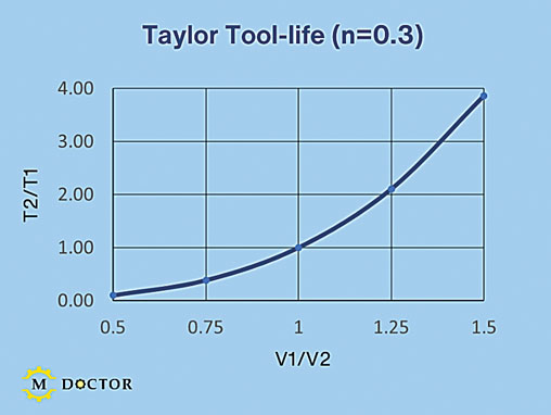
Taylor Tool-life (n=0.3)
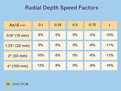
Radial Depth Speed Factors
Productivity versus tool life
There is a broad spectrum of cutting speeds that will work, and no single option is categorically correct or incorrect. Selecting a higher cutting speed to boost productivity may reduce tool lifespan. Conversely, a lower speed can extend tool life at the expense of productivity. Ultimately, the choice depends on your goals and personal preferences. Several models illustrate the relationship between cutting speed and tool life, with the Taylor model being the most widely used.
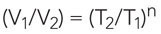
Where:
V1=Current cutting speed
V2=New cutting speed
T1=Current tool life
T2=New tool life
n=Material factor
Radial Depth & Cutting Speed
The typical value of n for carbide grades ranges from 0.2 to 0.4, influenced by the specific grade and the raw materials involved. The "Taylor Tool-life" graph features a Taylor model with n set to 0.3 is shown. The graph indicates that a 50% decrease in cutting speed can allow a tool to last up to 10 times longer. A 50% increase in cutting speed can lead to a 75% reduction in tool life. While the exact figures may differ among various materials, the key point is that cutting speed exponentially affects tool life.
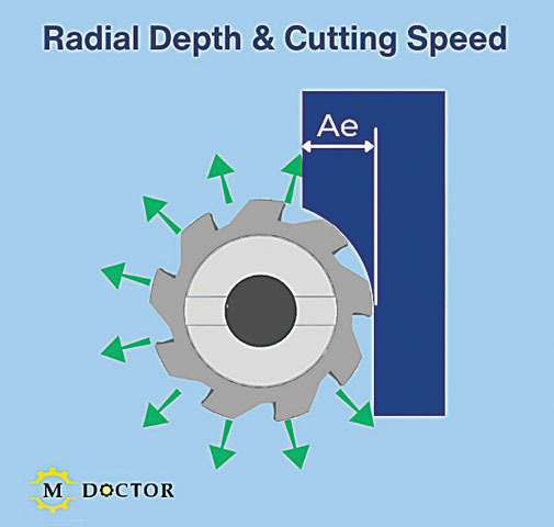
Milling radial depth of cut
In milling, it's crucial to consider the radial depth of cut (Ae). When this depth is less than the cutter's radius, the feed rate can be increased due to chip thinning principles. However, it's also important to note that the cutting speed can also be boosted. A smaller radial depth allows for more cooling time for each flute, facilitating this speed increase (see the "Radial Depth & Cutting Speed" illustration). The maximum speed increase depends on the cutter's diameter and the ratio of the radial depth to that diameter (Ae/d). Typically, catalog recommendations are based on an Ae/d value of 0.5, indicating that the radial depth matches the cutter's radius. Please refer to the "Radial Depth Speed Factors" table for detailed speed adjustments.
Editor's note: The information provided in this article is not scientific. However, it can be helpful in fine-tuning cutting speeds according to modifications in your application.


