Ream on

Author Christopher Tate
Published
October 20, 2022 - 11:00am

My machining education was quite different from most. Circumstances forced me to learn a lot on the fly, so broken tools, bloody fingers and scrapped parts were common on my journey.

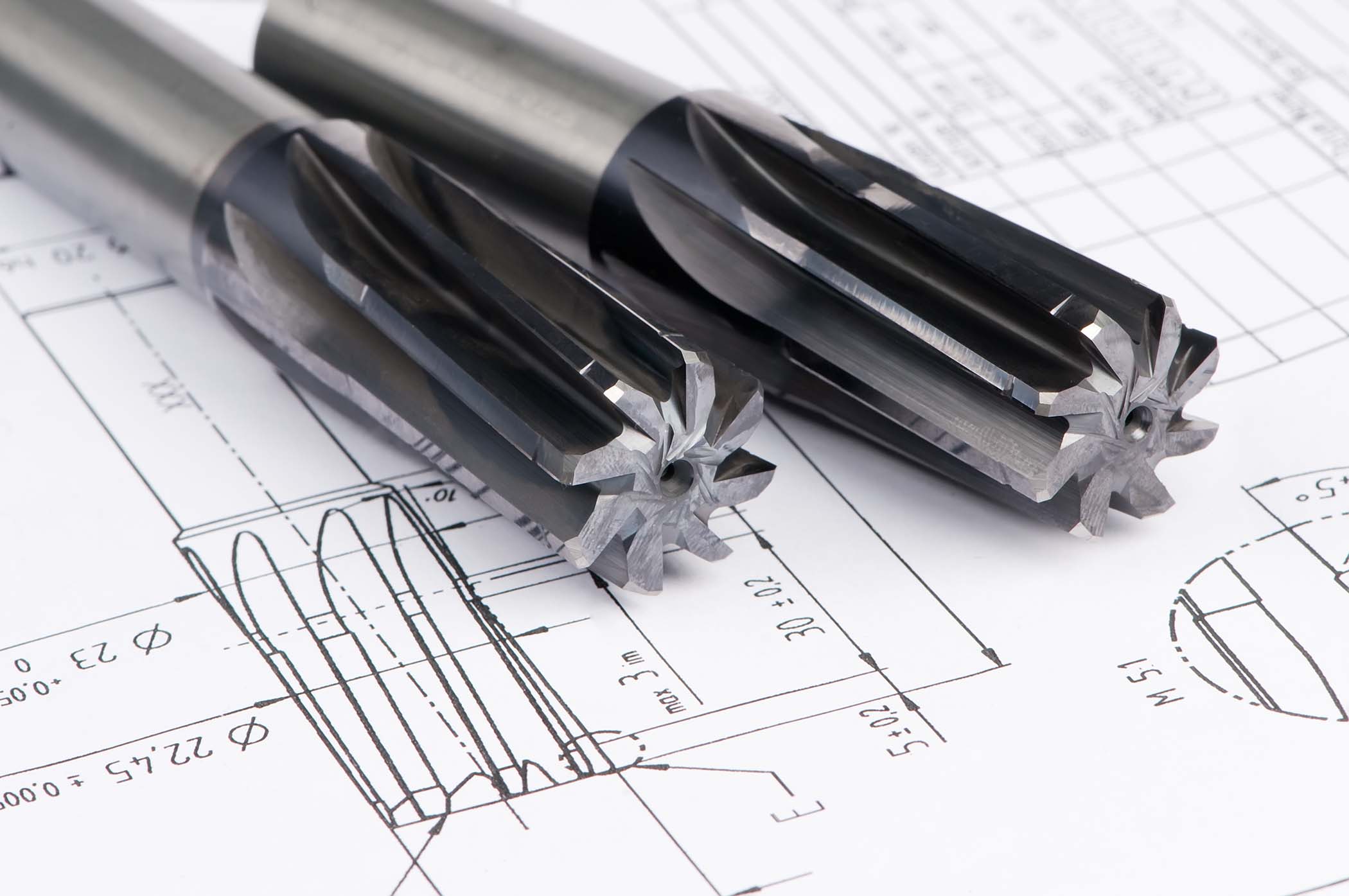
Learning to ream a good hole was one of the more difficult matters that I struggled with, and I learned much about what not to do. Fortunately, I was exposed to skilled people, and I managed to get short but effective lessons. With a little guidance from experienced toolmakers, I overcame the difficulties, and reaming high-quality holes became easy.

My first mistake was thinking that reaming a hole was as simple as “drill the hole, ream the hole, and you’re done.” Generating the right-size hole with a reamer is more than simply sticking it in the hole. Several variables need to be considered before putting the reamer in the hole.

Like all machining operations, tool quality is important. Buy a cheap reamer, and you will regret it. Go ahead and purchase a high-quality reamer from a reputable manufacturer. In general, reamers manufactured in Germany, Japan or the United States are best.

Consider the tolerance of the hole, and buy the right size of reamer for the job. Reamers rarely cut undersize holes, so plan to ream a hole larger than the diameter of the reamer. It always is a good idea to buy one reamer sized to the lower limit of the tolerance band and one reamer sized to the nominal dimension. Starting with the smaller reamer is a good way to limit the risk of making a hole that can’t be corrected.

Ream on
An old guy once told me that a reamer was running too fast if I could not count the flutes as it spun.

Having the best-quality tool that is sized perfectly doesn’t ensure a good hole. Oversize holes are overwhelmingly the biggest problem with quality when reaming, and radial runout is the primary contributor to oversize holes. Eliminating runout can be done in a couple of ways, beginning with making sure the reamer is held in the best method possible. In some cases, this means using a good collet. In other cases, this might necessitate a high-quality chuck. No matter how it is held, if the reamer wobbles when it spins, you likely will end up with an oversize hole. One of the more creative solutions I have seen for combating runout is holding the reamer in a boring head so the reamer can be “dialed in.”

Runout of the reamer is only a problem when the reamer rotates on a mill or drill press. When used on a turning machine, the problem is alignment. Tailstocks and turrets hardly ever are aligned close enough to ream a good hole. This is one of the few times when holding the cutting tool in a rigid manner can be detrimental to the operation. Successfully reaming a hole on a turning machine often requires some type of toolholder that allows movement or “float.” If you are going to ream holes on a lathe — by which I mean a traditional two-axis — go ahead and purchase a floating ream holder before you start. The floating holder enables the reamer to overcome alignment issues and find the center of the hole.

Cutting speed is critical to successful reaming, and reamers like to cut slowly compared with other tools like drills and endmills. Manufacturer recommendations and Machinery’s Handbook are the best references for cutting speed, but a general rule is to run the reamer 50% to 80% slower than a drill. An old guy once told me that a reamer was running too fast if I could not count the flutes as it spun.

Reamers work best when only a small amount of material is removed, so having the right amount of stock after drilling is critical. As always, the manufacturer is going to provide the best recommendations, but you will succeed in most cases if the finish allowance for the reamer is 0.002" (0.05 mm) to 0.005" (0.13 mm) per side (radial depth of cut). Leaving too much material for finishing results in bad finishes, oversize holes and broken reamers.

Reamers are for sizing drilled holes, and reamers make good hole geometry even better. However, they cannot correct a poorly drilled hole. The drilled hole needs to be straight and round or else the reamer is not going to cut correctly. In this case, the result is usually an oversize hole. If the hole is not straight when drilled, it will not be straight after reaming.

Finally, lubricate the reamer. It doesn’t matter if you use coolant or oil — the reamer just needs something to prevent the tool from rubbing the inside of the hole. Softer materials are subject to galling when no fluid is in the hole. A good flow of coolant is also nice for washing away chips, which can become lodged in the flutes, causing bad finishes and broken reamers.

Like most things at a machine shop, if you ask 10 machinists how to do something, you will get 10 different answers, and each one will be the best solution. That said, these are the things that I think about when preparing to ream holes. I am sure that machinists and toolmakers would have varying opinions about my methods. However, the theories are sound and aligned to the best practices common among machinists and toolmakers. Select a good tool, minimize runout, run the reamer at the right speed, and don’t push too hard. 

Related Glossary Terms

  • bandsaw blade ( band)

    bandsaw blade ( band)

    Endless band, normally with serrated teeth, that serves as the cutting tool for cutoff or contour band machines.

  • boring

    boring

    Enlarging a hole that already has been drilled or cored. Generally, it is an operation of truing the previously drilled hole with a single-point, lathe-type tool. Boring is essentially internal turning, in that usually a single-point cutting tool forms the internal shape. Some tools are available with two cutting edges to balance cutting forces.

  • boring head

    boring head

    Single- or multiple-point precision tool used to bring an existing hole within dimensional tolerance. The head attaches to a standard toolholder and a mechanism permits fine adjustments to be made to the head within a diameter range.

  • chuck

    chuck

    Workholding device that affixes to a mill, lathe or drill-press spindle. It holds a tool or workpiece by one end, allowing it to be rotated. May also be fitted to the machine table to hold a workpiece. Two or more adjustable jaws actually hold the tool or part. May be actuated manually, pneumatically, hydraulically or electrically. See collet.

  • collet

    collet

    Flexible-sided device that secures a tool or workpiece. Similar in function to a chuck, but can accommodate only a narrow size range. Typically provides greater gripping force and precision than a chuck. See chuck.

  • coolant

    coolant

    Fluid that reduces temperature buildup at the tool/workpiece interface during machining. Normally takes the form of a liquid such as soluble or chemical mixtures (semisynthetic, synthetic) but can be pressurized air or other gas. Because of water’s ability to absorb great quantities of heat, it is widely used as a coolant and vehicle for various cutting compounds, with the water-to-compound ratio varying with the machining task. See cutting fluid; semisynthetic cutting fluid; soluble-oil cutting fluid; synthetic cutting fluid.

  • cutting speed

    cutting speed

    Tangential velocity on the surface of the tool or workpiece at the cutting interface. The formula for cutting speed (sfm) is tool diameter 5 0.26 5 spindle speed (rpm). The formula for feed per tooth (fpt) is table feed (ipm)/number of flutes/spindle speed (rpm). The formula for spindle speed (rpm) is cutting speed (sfm) 5 3.82/tool diameter. The formula for table feed (ipm) is feed per tooth (ftp) 5 number of tool flutes 5 spindle speed (rpm).

  • drilling machine ( drill press)

    drilling machine ( drill press)

    Machine designed to rotate end-cutting tools. Can also be used for reaming, tapping, countersinking, counterboring, spotfacing and boring.

  • flutes

    flutes

    Grooves and spaces in the body of a tool that permit chip removal from, and cutting-fluid application to, the point of cut.

  • galling

    galling

    Condition whereby excessive friction between high spots results in localized welding with subsequent spalling and further roughening of the rubbing surface(s) of one or both of two mating parts.

  • lathe

    lathe

    Turning machine capable of sawing, milling, grinding, gear-cutting, drilling, reaming, boring, threading, facing, chamfering, grooving, knurling, spinning, parting, necking, taper-cutting, and cam- and eccentric-cutting, as well as step- and straight-turning. Comes in a variety of forms, ranging from manual to semiautomatic to fully automatic, with major types being engine lathes, turning and contouring lathes, turret lathes and numerical-control lathes. The engine lathe consists of a headstock and spindle, tailstock, bed, carriage (complete with apron) and cross slides. Features include gear- (speed) and feed-selector levers, toolpost, compound rest, lead screw and reversing lead screw, threading dial and rapid-traverse lever. Special lathe types include through-the-spindle, camshaft and crankshaft, brake drum and rotor, spinning and gun-barrel machines. Toolroom and bench lathes are used for precision work; the former for tool-and-die work and similar tasks, the latter for small workpieces (instruments, watches), normally without a power feed. Models are typically designated according to their “swing,” or the largest-diameter workpiece that can be rotated; bed length, or the distance between centers; and horsepower generated. See turning machine.

  • milling machine ( mill)

    milling machine ( mill)

    Runs endmills and arbor-mounted milling cutters. Features include a head with a spindle that drives the cutters; a column, knee and table that provide motion in the three Cartesian axes; and a base that supports the components and houses the cutting-fluid pump and reservoir. The work is mounted on the table and fed into the rotating cutter or endmill to accomplish the milling steps; vertical milling machines also feed endmills into the work by means of a spindle-mounted quill. Models range from small manual machines to big bed-type and duplex mills. All take one of three basic forms: vertical, horizontal or convertible horizontal/vertical. Vertical machines may be knee-type (the table is mounted on a knee that can be elevated) or bed-type (the table is securely supported and only moves horizontally). In general, horizontal machines are bigger and more powerful, while vertical machines are lighter but more versatile and easier to set up and operate.

  • reamer

    reamer

    Rotating cutting tool used to enlarge a drilled hole to size. Normally removes only a small amount of stock. The workpiece supports the multiple-edge cutting tool. Also for contouring an existing hole.

  • tolerance

    tolerance

    Minimum and maximum amount a workpiece dimension is allowed to vary from a set standard and still be acceptable.

  • toolholder

    toolholder

    Secures a cutting tool during a machining operation. Basic types include block, cartridge, chuck, collet, fixed, modular, quick-change and rotating.

  • turning

    turning

    Workpiece is held in a chuck, mounted on a face plate or secured between centers and rotated while a cutting tool, normally a single-point tool, is fed into it along its periphery or across its end or face. Takes the form of straight turning (cutting along the periphery of the workpiece); taper turning (creating a taper); step turning (turning different-size diameters on the same work); chamfering (beveling an edge or shoulder); facing (cutting on an end); turning threads (usually external but can be internal); roughing (high-volume metal removal); and finishing (final light cuts). Performed on lathes, turning centers, chucking machines, automatic screw machines and similar machines.

  • turning machine

    turning machine

    Any machine that rotates a workpiece while feeding a cutting tool into it. See lathe.

Sponsored Content