



In the (Small) Groove: Turning Performance
Grooving miniature parts requires a conservative cutting approach and a choice between solid-carbide and insertable tools.
Grooving miniature parts requires a conservative cutting approach and a choice between solid-carbide and insertable tools.
Small parts require even smaller grooves. That simple idea is driving one of the ongoing trends in grooving—the need to design and apply tools that can cut a variety of grooves in a growing number of miniature parts. The challenge is to design tiny tools and develop cutting strategies that resist tool breakage and manage chip generation in tight spaces.
“One of the biggest changes we’ve seen is in the minimum bore sizes [the bore size that a grooving tool can fit into],” said Duane Drape, national sales manager, HORN USA Inc., Franklin, Tenn. “Four years ago, our minimum bore for grooving was 4mm. Now we have off-the-shelf 2mm minimum-bore grooving tools, and some customers are requesting off-the-shelf tools for grooving down to 1mm. Our smallest standard minimum-diameter tools are 0.2mm, but they are for boring, not grooving. We are constantly getting calls to reduce diameters even further.”
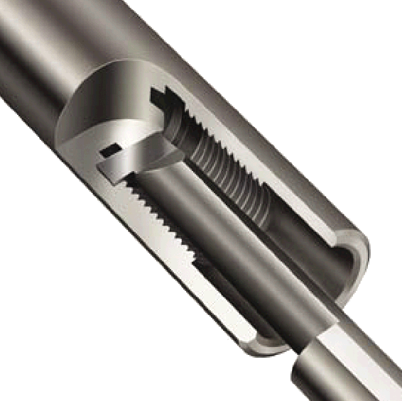
Courtesy of Thinbit
A Microbit ID grooving tool from Thinbit for diameters 0.125 ” and larger.
How Small is Small?
According to Andy Kelling, national product manager, screw machines, Iscar Metals Inc., Arlington, Texas, the overall length of most miniature parts that require grooving ranges from 1mm to 25.4mm, with diameters starting at 0.2mm. These parts are used in dental implants, stents, probes, instruments, electrodes, injectors, small fasteners and internal valve body components.
Other miniature grooving applications include fittings for automotive airbag components, fuel injection components, aerospace components and spray nozzles.
There are various grooves and grooving techniques required for miniature parts. According to Ken King, COO of Thinbit/Kaiser Tool Co. Inc., Fort Wayne, Ind., grooving miniature parts requires determining what the grooves will be used for, what types of grooves are needed and what types of geometries the grooves must have. In miniature part production, grooves are typically for connecting parts (snap rings), sealing mating surfaces (O-rings), thread relief, holding lubrication and reducing surface contact. Types of grooves include OD and ID grooves, face grooves and angled grooves. “Grooves can blend into other features and multifunction tools can produce more than grooves, so creating a definition can be tricky, but grooves can have chamfers, radii and angles,” said King.
Grooving Challenges
According to Drape, the main challenge for ID grooving in miniature parts is the tiny tools’ relative lack of strength. “When you are going into a 1mm bore, you need a tool that has to fit axially into that 1mm bore and then apply radial force to [the bore]. This cutting pressure typically tries to bend the tool dramatically, causing form and chatter problems as well as tool breakage and chip evacuation issues,” he said.
A typical solid-carbide grooving tool looks like an L, and the leg (noncutting) portion has to fit within the bore diameter. For a 2mm bore, that means the most the noncutting edge can be is 2mm minus a clearance. The foot portion of the L-shape has to be even smaller than the leg portion, which weakens it dramatically. Small-diameter bores also limit groove depth. “If you want to put a groove in a 2mm-dia. bore, the most tmax (radial DOC) is 0.2mm,” said Drape. Consider the machining of a 2mm bore. A grooving tool with a 1mm leg would require a safety factor of 0.2mm between the leg and the component. Theoretically, then, the tool could cut a 0.8mm-deep groove. However, with only 1mm of leg, the tool will probably be too weak to actually cut a groove of that depth, and would be limited instead to a 0.2mm groove depth, said Drape.
Applying small grooving tools requires a different machining approach, including much lower feed rates than with larger grooving tools, said Drape. “You need to slow the feed rate down so as not to put too much pressure on the tool and break it,” he said. Typical feed rates for miniature grooving tools with 2mm to 6mm minimum bore sizes are from 0.0002 to 0.0008 ipr. Drape added that tool monitoring is essential when using tiny grooving tools because it is hard to visually or audibly detect a broken tool when the cutting edge is so small.
Small grooving operations also present chip-form and chip-flow challenges, according to Larry Myers, vice president of operations for Denitool Inc., Murfreesboro, Tenn. “It is desirable to compress the width of the chip to insure that it does not lodge in the groove being produced, which can stop chip flow and cause catastrophic failure,” he said.
Myers added that guiding a continuous grooving chip from the cutting zone is important because a broken chip can lodge in the workpiece and fracture the insert. “This process is critical on small bores where the cutting tool is smaller, the room for chip evacuation is limited and the grooves are deep inside a bored hole,” he said.
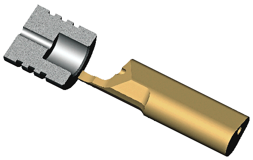
Courtesy of HORN
A 6mm-dia. face grooving operation.
Chip management factors include insert and chipbreaker geometry as well as the feeds, speeds and toolpath. “In all grooving operations [including threading], cutting pressure is very high compared to other cutting [operations] because of the length of the cutting edge required to make the groove and the confined chip-removal space,” said Myers. “The reduction of this cutting pressure is critical to successful grooving and can be accomplished mainly by using proper feeds and speeds, tool design and lubricants.” The recommended speeds and feeds depend on the type and hardness of the workpiece material, according to Myers. He recommends lubricants with high lubricity for miniature part applications.
Inserts or Solid Carbide?
Another issue when grooving miniature parts is the choice between insertable and solid-carbide tools. Many shops like to use inserts whenever possible due to their lower unit costs, but there are size limitations and other considerations that factor into the decision (see sidebar on page 61).
When making this choice, “first define an insert,” said HORN’s Drape. “There are many types of inserts available. Some are indexable [with multiple cutting edges] and others are single use.”
Using an indexable insert for grooving is limited by bore diameter. In most cases, the smallest bore diameter for these types of tools is 0.708 “, according to Drape. There may be indexable tools for smaller bores but the radial DOC achievable with such tools is typically less than 0.040 “.
“That being said, you still can use a replaceable insert tool for grooving in bores as small as 0.300 ” in diameter,” Drape said. “These are usually single-edge replaceable inserts, but they provide a greater axial depth into the component and a more reasonable cost for longer reaches than a solid-carbide tool could provide.”
Solid-carbide tools are preferable for the smallest bores, but shops should keep in mind that some manufacturers, HORN included, call small solid-carbide tools inserts because they typically require a specific toolholder, said Drape.
According to King of Thinbit, solid-carbide tools are typically preferred in most ID grooving applications under 0.500 “. While these tools are more expensive, they are stronger. “With inserts, you must reduce the strength of the toolholder to have a clamping mechanism for the insert and a place to mount the insert,” said King. This is not required for small solid-carbide grooving tools.
Still, he agreed that it is generally best to use inserts whenever possible due to cost concerns. “Most [grooving tool] manufacturers go down to 5/16 “, or an 8mm bore diameter, with inserts,” said King. “Regarding groove width, we go to 0.004 ” as a standard size and offer every 0.001 ” increment to 0.250 “. The trend is to smaller parts that require smaller grooves.”
Myers of Denitool agreed that indexable grooving inserts should always be considered when the part or bore size permits access. He noted that Denitool’s smallest insert grooving system can enter a 0.150 ” bore. “Insert inscribed circle sizes produced by Denitool have decreased over the past 5 years,” said Myers. “Our partnerships with key customers worldwide have indicated a clear need for development in this area.”
Types of Grooving
While there are many types of grooving operations that can be performed on miniature parts, an end user first needs to define grooving. “HORN defines a grooving operation as any operation removing material between two flanks,” Drape said. “Keeping your mind open, this means:
• threading—constant helical groove,
• parting off—grooving until no more material,
• forming—consists of a groove and possibly some OD or ID cutting, and
• broaching—groove or form placed axially, not radially.”
He added that the most commonly used operations on miniature parts include ID and OD grooving of seals, ID and OD threads, relief grooves for mating components and broaching of keyways, hexes, squares and Torx features.
OD grooving is easiest to generate by side turning or plunging, starting at around 0.020 ” wide, according to Iscar’s Kelling. For this application, Iscar recommends its PENTACUT insert with five cutting edges and a molded chipformer.
For ID grooving and undercutting, the company recommends a coolant-feed, solid-carbide insert, starting at a 0.002 ” radius and a 0.024 ” ID.
For face grooving miniature parts, Iscar recommends its standard solid-carbide inserts, which start at 1mm wide and an ID of 0.236 “.
Special application methods recommended by Iscar use face forming and trepanning inserts to produce intricate forms containing grooves on the ends of some parts. Also, a multifunction tool that performs slotting and grooving has been used in several applications, according to Kelling. “When applications are reviewed, the focus is on using the fewest cutting tools,” said Kelling. “This decreases the required number of cutting tools, tool stations and tool change times, which reduces tooling costs along with machining cycle time.”

Courtesy of Iscar
OD grooving, such as parting off, can be performed with a PENTACUT tool with five cutting edges and a molded chipformer.
While many shops purchase off-the-shelf grooving tools for miniature part applications, larger manufacturers that use high volumes of these tools may purchase blanks and grind their own tools. “We offer our Micro-Mini solid-carbide grooving tools that can be made into specials,” said Chris Wills, product specialist, Mitsubishi Materials USA Corp., Schaumburg, Ill. “Our customers do the finishing work themselves. Higher-end users will have a high-precision grinder, or they will send it to a supplier and have them custom made,” he said.
The Micro-Mini tool line is offered in widths of 1mm and 2mm with radii down to 0.05mm. Shank sizes vary depending on the round shank holders on the machine they are used for. Standard groove widths for Mitsubishi’s indexable GTAT grooving insert line are 0.3mm to 3.0mm (0.012 ” to 0.118 “).
Machine Tools
Manufacturers of miniature parts typically use Swiss-type and multiple-spindle machines, but any machine—including smaller CNC lathes—that can hold the part and the tooling can produce such parts.
“Small parts usually have tight tolerances, so machine accuracy is important,” said Thinbit’s King. Small parts also rotate at a high rpm. The formula is (sfm × 12)/(π × diameter). That means a ½ “-dia. part has to rotate at twice the speed as a 1 ” part.
With products such as medical implants, high-precision fuel injectors and electronics like the iPod growing in popularity, the growth trajectory for miniature parts will continue. These devices are not only getting smaller, they are also packed with more components. Grooving is one of the many metalcutting applications that will enable manufacturers to meet the growing demand for high-precision parts that make these devices work. CTE
About the Author: Alan Rooks is editorial director for Cutting Tool Engineering. He has been a business journalist for the past 27 years. Contact him at (847) 714-0174 or by e-mail at arooks@jwr.com.
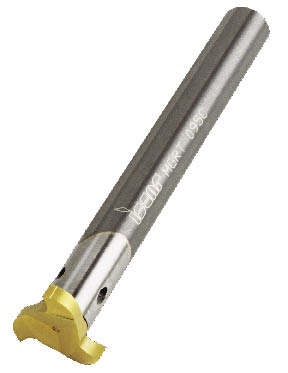
Courtesy of Iscar
Tools such as this Multi-Master can perform multiple grooving operations.
Using multifunction tools for grooving
One way to reduce setup and machining time when grooving miniature parts is to use multifunction tools, such as one that performs slotting, endmilling, OD grooving and thread milling. One such tool is the Iscar Multi-Master. “There are applications where we can use one tool to do multiple operations, mainly on an OD or face groove,” said Andy Kelling of Iscar Metals Inc. “If you’re end slotting, you can also groove if you orient the tool a different way, pick the part off on a Swiss-style machine and machine with an auxiliary spindle. The goal is to minimize the number of tools used in setup.” He noted that the Multi-Master can groove full radiuses and create flat-bottom grooves, notch grooves and other intricate grooves.
One parts manufacturer used the Multi-Master to make grooves in a 3 “-long dental probe on a Tsugami Swiss-style machine. The part is made of 17-4 PH heat-treated stainless steel and its largest diameter is 0.160 “. The instrument point tapers to a 0.0008 ” tool-generated radius. The OD perpendicular groove and an OD parallel slot are both made with the same MM GRIT Multi-Master 0.020 “-wide insert. The parallel slot is about 0.750 ” in length along two diameters. The 0.020 “-wide perpendicular groove on the rear OD was generated by the same rotating MM GRIT Multi-Master insert after picking off on the machine’s subspindle end. Grooving and slotting time decreased by 60 percent compared to the original process developed by another supplier, which used three tools.
— A. Rooks
Solid-carbide tools or inserts?
One of the key decisions in grooving miniature parts is whether to use indexable or single-point inserts or solid-carbide tools. Duane Drape of HORN USA Inc. has some specific guidelines for shops to consider.
“We don’t go below 0.300 ” in diameter with an insertable grooving tool,” he said. “There are insertable tools on the market below 0.300 “, but consider that an insert tool requires a pocket, so now you have a piece of carbide to be held down by a setscrew, and that piece of carbide has to have a certain amount of thickness to it. Once you machine that pocket, you have a very weak area in the front of the tool where the insert seats. You can’t necessarily apply the proper geometries to that insert. So, will tools like that work on a specific miniature application? Absolutely. But there could be a quality issue.”
Another issue to consider is price. Solid-carbide tools typically have a higher unit price, but Drape argues that shops should consider the total application cost for grooving a miniature part before making a decision.
“Some people are put off by the fact that a solid-carbide tool in some situations can cost $70, while an insert with three cutting edges costs just $12,” said Drape. “But that $12 insert goes into a $300 to $400 toolholder, and since the holder is very small, it is relatively weak and has to eventually be thrown away, possibly after using 10 inserts. When you add up those costs, your price is getting very comparable to solid carbide, and if you don’t get 10 uses out of a holder, and you get just one or two, the total cost is a lot more.”
In addition, the repeatability of an insert below 0.300 ” in diameter will not be as accurate as a solid-carbide tool, said Drape. “We’re not saying that inserts are bad in these kinds of applications,” he said. “However, shops using them might have to fight these kinds of problems. That’s why we stay with solid-carbide tools for grooving applications requiring tools below 0.300 ” in diameter.”
—A. Rooks
Contributors
Denitool Inc.
(615) 867-8882
www.denitool.com
HORN USA Inc.
(888) 818-4676
www.hornusa.com
Iscar Metals Inc.
(877) BY-ISCAR
www.iscarmetals.com
Thinbit/Kaiser Tool Co. Inc.
(888) THINBIT
www.thinbit.com
Mitsubishi Materials U.S.A. Corp.
(800) 523-0800
www.mitsubishicarbide.com
Glossary terms in this article
Related




Subscribers can use MFGAxis notes, saves and discussion tools with their innoNET account.


