Three rules for cutting thin parts
In recent years, monolithic machined aluminum components have been replacing sheet metal assemblies throughout the aerospace industry.
In recent years, monolithic machined aluminum components have been replacing sheet metal assemblies throughout the aerospace industry. The monolithic structures are lighter, less expensive and stronger than their conventional sheet metal counterparts. Machining the components requires fewer special tools, fewer hand operations and less assembly time.
R&D in this area began in the 1970s with testing of high-speed machining theories. At that time, ballistic machining tests, where the cutting tool shot past the workpiece as a projectile, made it clear that solid-carbide tools would be quite capable of surviving the cutting temperatures when machining aluminum. However, a new class of machine tools would be required to support those cutting tools.
Courtesy of S. Smith
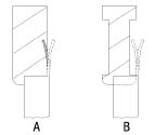
Figure 1A: Machining a thin wall occurs as the tool tip removes material at the base of the wall, where the wall is stiff.
Figure 1B: To avoid cutting through a thin wall, apply a tool with its cutting teeth removed from the portions of the tool where no machining is intended.
In the 1980s, as spindles and machine tools became faster, the development of reliable chatter prediction tools began to dominate HSM research, and the drive to simplify the tools for chatter avoidance became a powerful force.
Review the print ads from this magazine to continue
This quick advertiser review unlocks the rest of the article and keeps the full-screen reader focused on the ads instead of the page chrome.


MFGAxis Discussion