

Tools With Abrasive Personalities
Machining polymeric composite materials with single-layer diamond abrasive tools.
Machining polymeric composite materials with single-layer diamond abrasive tools.
[Editor’s Note: A study of machining polymeric composite materials (PCM) with diamond abrasives conducted by Ukrainian scientists resulted in the development of tools, such as cutoff wheels, grinding wheels, rollers, grinding heads, drills and countersinks, made of superhard materials along with verifiable recommendations for their applications. The study defined conditions that maximize machining productivity and improve the surface finish quality of PCM.]
The unique physical, mechanical and thermo-physical properties of PCM make them useful for the aerospace, marine and automotive industries. These materials contain two or more components (separate fibers or other reinforced elements bound by a polymeric thermo-reactive matrix) and possess specific properties, which are different than the combined properties of their components.
All images: “ALKON”
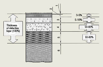
Figure 1: Schematic formation of broken and dispersible superficial layer of PCM machined with abrasive diamond tools.
1. Adsorbed film (less then 1μm, or 40μin.)
2. Modified layer (0.05μm to 5μm, or 2 to 200μin.)
3. Broken layer (3μm to 7μm, or 120 to 280μin.)
4. Dispersible crushed and disintegrative layer (10μm to 150μm, or 0.0004 ” to 0.006″)
5. Transitional layer (15μm to 50μm, or 0.0006 ” to 0.002 “)
6. Original texture of PCM
Normally, after being produced, PCM parts undergo machining operations, which consume 10 to 50 percent of the total production time. The most common operations are cutting off and grinding.
While it wouldn’t seem that relatively soft polymeric composites comprised of fiberglass, carbon and other materials should be difficult to cut, machining does cause significant problems in full-scale production:
• High temperatures in the cutting zone reach the heat-resistance level of HSS tools and the polymeric component;
• Rapid wear of the cutting tools shortens the tool life typically seen when machining steels and other alloys; and
• The machining process generates toxic gaseous agents and fine dust that are easily dispersed and can contaminate the work environment.
These and other peculiarities associated with cutting PCM should be considered when designing PCM parts, developing machining processes, identifying appropriate cutting tools and selecting optimal cutting parameters.
Cutting PCM always creates a defective (broken and dispersible) superficial layer of the workpiece surface (Figure 1). It is impossible to eliminate formation of this layer, but it’s possible to manage its development.
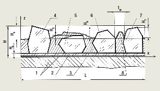
Figure 2: Schematic of a cross section of a composite diamond-electroplated coating.
1. Copper-electroplated metallic tool body
2. Intermediate diamond-free layer
3. Nickel binder
4, 5, 6 and 7. Synthetic diamonds retained in a single layer by electroplating
8. Binder overhang above its basic level
Hi (i = 4-7). Diamond overhang above the binder
H0. Thickness of the no-diamond layer
1ai. Distance between diamond grains
The defective superficial layer is identified by its color. Resin-based polymeric composite materials are dark and, depending on the destruction’s depth and degree, their surfaces usually become ashy and sometimes gray. The defective surface of bright, layered plastics, especially fiberglass-based ones, becomes dark with a grayish-yellow shade from the nondefective surface. The cutting tool’s feed rate affects the depth of the defective superficial surface three times as much as the cutting speed.
The following relationship was established: an increase in machining productivity increases the cutting temperature, decreases tool life and reduces surface finish quality.
The total depth of defective, disintegrative and transitional layers depends on the cutting conditions and varies from 20 to 200 microns (0.0008 ” to 0.008 “) when applying diamond abrasives. This is about 10 times less than the depth produced by conventional blade-type cutting tools.
Increasing Machining Effectiveness
More effective machining of PCM requires the development of highly productive technology and reliable, long-lasting and wear-resistant cutting tools with synthetic diamonds, which offer superior thermal conductivity and wear and abrasion resistance. This guideline is based on scientific, engineering and technologic studies conducted at the V.N. Bakul Institute for Superhard Materials and Scientific and Technological Diamond Concern of the Ukrainian National Academy of Sciences.
R&D efforts have shown that distribution of synthetic diamond grains in a single layer and retention of the grains by electroplating is effective for diamond tools that machine PCM.
Optical and electronic microscopy were used to evaluate the physical phenomena of the cutting process and how it affects a diamond layer and the regularities of forming and changing a cutting tool’s contact area with the workpiece material.
Table 1: Principal dimensions of single-layer diamond cutoff wheels and their cutting elements (dimensional symbols are shown in Figure 3)
| Dimensions of the wheels and their elements, mm | Number of cutting elements, n | |||||
|
D |
d |
h |
h1 |
a |
b |
|
|
90 |
12 |
1.0 |
3.0 |
2.0 |
4.0 |
47 |
|
90 |
12 |
1.0 |
3.0 |
1.0 |
2.0 |
94 |
|
125 |
32 |
1.2 |
3.5 |
1.0 |
2.0 |
131 |
|
125 |
32 |
1.2 |
3.5 |
2.0 |
3.0 |
79 |
|
160 |
32 |
1.8 |
3.5 |
1.0 |
2.0 |
167 |
|
160 |
32 |
1.8 |
3.5 |
2.0 |
4.0 |
84 |
|
200 |
32 |
1.8 |
4.0 |
1.0 |
2.0 |
209 |
|
200 |
32 |
1.8 |
4.0 |
3.5 |
7.0 |
60 |
|
250 |
32 |
1.8 |
4.0 |
1.5 |
3.0 |
174 |
|
250 |
32 |
1.8 |
4.0 |
5.0 |
10.0 |
53 |
|
320 |
32 |
2.2 |
5.0 |
1.5 |
3.0 |
223 |
|
320 |
32 |
2.2 |
5.0 |
5.0 |
10.0 |
67 |
Review the print ads from this magazine to continue
This quick advertiser review unlocks the rest of the article and keeps the full-screen reader focused on the ads instead of the page chrome.
Advertisers included in this article experience
Print placements connected to this article
Mastercuttool
IS #38 IS #97
ROTARY CUTTING TOOLS CUTTING EDGE TECHNOLOGY Meeting all of your Solid Carbide Cutting Tool needs with a large inventory of : Endmills - Burs - Drills - Reamers - Routers and High-performance tools. Catalogs available in Fractional and Metric ranges. 965 F. Harbor Lake Drive - Safety Harbor - FL 34695 IS #57 IS #42.
IS #38 IS #97 ROTARY CUTTING TOOLS CUTTING EDGE TECHNOLOGY Meeting all of your Solid Carbide Cutting Tool needs with a large inventory of : Endmills - Burs - Drills - Reamers - Routers and High-performance tools. Catalogs available
Visit Mastercuttool View this placement in the issue recordPrint ads from this magazine
ROTARY CUTTING TOOLS CUTTING EDGE TECHNOLOGY Meeting all of your Solid Carbide Cutting Tool needs with a large inventory of : Endmills - Burs - Drills - Reamers - Routers and High-performance tools. Catalogs available in Fractional and Metric ranges. 965 F. Harbor Lake Drive - Safety Harbor - FL 34695 IS #57 IS #42.
IS #38 IS #97 ROTARY CUTTING TOOLS CUTTING EDGE TECHNOLOGY Meeting all of your Solid Carbide Cutting Tool needs with a large inventory of : Endmills - Burs - Drills - Reamers - Routers and High-performance tools. Catalogs available
Continue reading
March 2009
Recommended machining conditions for cutting off various PCM with single-layer diamond abrasive tools are shown in Table 2.
The surface of a single-layer diamond abrasive tool is a rough, complex and multiphase heterogeneous system. Such a system contains dielectric diamond grains strongly connected to each other and safely retained in the binder (Figure 2).
The copper-electroplated metallic body and the intermediate diamond-free layer provide high adhesion strength between the diamond layer and tool body.
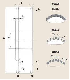
Figure 3: Single-layer diamond abrasive cutoff wheel with outside cutting edge.
The acting surface’s profile of a single-layer diamond wheel is based on the grain size of the synthetic diamond powder (d measured in μm), the number of diamond grains per unit of area (n measured in pieces/mm2), the distance between the grains (lai measured in mm) and the geometric shape of the diamond grains overhanging the binder.
Thirty-six cutting elements of a diamond wheel were studied. Those elements had diamonds with average grain sizes from 200μm/160μm to 1,000μm/800μm. Diamond powders of the narrow range (75 to 80 percent of the main fraction, or average grain size) were used. Certain restrictions were applied: specific electric resistance was 1010 ohm × m or higher, and the diamond grain surface didn’t contain any electro-conductive impurities.
The results of these studies showed that the number of diamond grains per wheel surface unit and the distance between them depend on grain size. If the grain size increases, the number of overhanging diamonds in the wheel decreases and the distance between grains increases. The average distance (lai measured in μm) between the diamond grains for the range studied was lai = (0.6 to 0.8) × dav, where dav is an average cubed size grain within the major fraction.
A large measuring microscope (50×) was used to evaluate diamond grain shapes. About 75 percent of diamond grains measured in the wheel’s axial plane had trapezoidal contours, and the diamond grains measured in the binder plane looked like rectangles, almost like squares, i.e., the diamonds overhanging the binder looked like a regular quadrilateral frustum of a pyramid.
Fabrication of the cutting tool’s active layer by the galvanic method forms a cutting surface in which diamond grains are overhung by 33 to 67 percent of their average size, i.e., Hi = (0.33 to 0.67) × d, where d is the average size of a diamond grain measured in μm. Cutting force, high temperature, impact loads, vibration and wear reduce the overhangs of the diamond grains to the range of Hi = (0.45 to 0.55) × d. Each grain size is characterized by the optimal height of synthetic diamonds’ overhang, so the maximum cutting productivity is achieved while the diamonds wear.
Based on the main geometric shape of the diamond grains’ overhang above the wheel’s binder and taking into consideration a “cylinder-plane” contact (typical for plane grinding by a wheel’s periphery), the nominal contact area of the diamond grains, binder and wheel was determined by an analytical method.
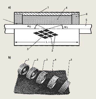
Figure 4: Design of a single-layer diamond abrasive roller: a) the roller and b) the wheels with different geometry of the interrupted cutting surface.
Single-layer diamond abrasive tools with a nickel-galvanic binder developed at the Institute for Superhard Materials, including cutoff and grinding wheels, rollers, grinding heads, drills and conical and cylindrical countersinks, are based on the principles of minimizing the thermal fields in the tool/workpiece cutting zone and optimizing clearance of the contact between the tool and workpiece. In accordance with these principles, reduction of thermal stresses generated by such tools when cutting PCM can be achieved at certain periods of time. The durations of such periods should be shorter than when heat saturates the workpiece.
To obtain such a condition, calculations of thermal fields in the workpiece and in the cutting tool were performed. Based on these calculations, the following design and geometric parameters of the interrupted working surface were determined: dimensions of the cutting elements, the distance between them and inclination angles of the cutting elements respectively to the tool’s centerline.
From a design viewpoint, the working surface of the recommended diamond abrasive tools is a sequence of alternate overhangs and recesses. The dimensions of the overhangs and recesses are determined through the amount of time of the cutting elements’ engagement and disengagement with the workpiece. The design of the cutting elements provides optimal clearance between the cutting tool and workpiece to wash microchips from the cutting zone.
Tests were conducted to determine the relationship between the shape of diamond tools’ working surface compared to characteristics of their cutting elements and PCM types. These findings were utilized to determine optimal cutting parameters and their influence on productivity, part quality, machining accuracy and diamond tool life.
Recommended Tool Dimensions
Cutting PCM, such as 20mm (0.79 “)-thick sheets and tiles with carbon, boron, organic or fiberglass components and up to 60mm (2.36 “)-thick structures made of honeycomb fillers, is performed by single-layer diamond abrasive wheels in diameters from 90mm to 400mm (3.54 ” to 15.75 “) made of 1.0mm to 2.2mm (0.04 ” to 0.09 “)-thick discs.
The recommended spindle speeds are 3,000 to 6,000 rpm for machine tools and 4,000 to 10,000 rpm for hand-held pneumatic tools when cutting PCM. The recommended feed rate is from 0.6 to 12 m/min. (2 to 40 sfm). Vertical movement of the table or the spindle to obtain the required DOC is performed manually or by a mechanical drive.
Table 2: Recommended cutting conditions and characteristics of diamond tools
| Cutting conditions* | Characteristics of diamond tools | ||||
|
u, m/s (sfm) |
S, m/s (ft./min.) |
t, mm (in.) |
Type of wheel |
Diamond grade |
Grain size |
| Cutting off carbon and fiberglass plastics and honeycomb fillers | |||||
|
30-35 (5900-6890) |
0.01-0.06 (2.0-12.0) |
15.0-20.0 (0.59-0.79) |
1A1RSS/C1 |
AC15 |
500/400 |
|
35-40 (6890-7870) |
0.06-0.10 (12.0-20.0) |
10.0-15.0 (0.39-0.59) |
400/315 |
||
|
35-40 (6890-7870) |
0.10-0.15 (20.0-30.0) |
4.0-10.0 (0.16-0.39) |
|||
| Cutting off organic fiberglass plastics | |||||
|
30-35 (5900-6890) |
0.01-0.06 (2.0-12.0) |
15.0-20.0 (0.59-0.79) |
1A1RSS/C2 |
AC20 |
630/500 |
|
30-35 (5900-6890) |
0.06-0.10 (12.0-20.0) |
10.0-15.0 (0.39-0.59) |
500/400 |
||
|
35-40 (6890-7870) |
0.10-0.15 (20.0-30.0) |
4.0-10.0 (0.16-0.39) |
400/315 |
||
| Cutting off organic plastics | |||||
|
30-35 (5900-6890) |
0.03-0.06 (6.0-12.0) |
15.0-20.0 (0.59-0.79) |
1A1R |
AC32 |
630/500 |
|
30-35 (5900-6890) |
0.06-0.08 (12.0-16.0) |
10.0-15.0 (0.39-0.59) |
|||
|
35-40 (6890-7870) |
0.08-0.10 (16.0-20.0) |
4.0-10.0 (0.16-0.39) |
* Symbols of the cutting parameters are:
u = cutting speed (m/s, meters per second)
S = machine feed rate
t = DOC
Service life of diamond cutoff wheels measured in the total area of cut and expressed in m2 (ft.2) is shown in Table 3.
Applying diamond wheels with nickel-galvanic binder for cutting off PCM provides the following benefits:
• Service life is five to seven times longer than that for diamond wheels manufactured by P/M methods;
• Machining productivity increases two and a half to three times;
• The quality of the machined surface is improved (thermal destruction of polymeric components is minimized), and burns, edge chippings, scaling and other defects on machined surfaces are eliminated. The imparted surface roughness is 20μm Rz to 40μm Rz ( equivalent to 4μm Ra to 8μm Ra or 160 μin. Ra to 320 μin. Ra because Rz ≈ 5 Ra).
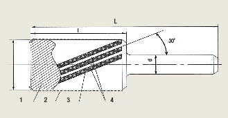
Figure 5: Design of a single-layer diamond grinding head: 1) body 2) working surface 3) grinding elements and 4) grooves.
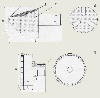
Figure 6: Design of single-layer diamond abrasive solid (a) and annular (b) drills: 1) body and 2) working surfaces.
Cutting Off, Grinding
During the aircraft assembly process, for example, it is necessary to trim a technological allowance to cut off the apertures. For this job, “ALKON” offers single-layer diamond abrasive hacksaws. A 1.2mm (0.05 “)-thick steel blade has a diamond-containing layer. The cutting edges are either solid or interrupted. AC20-grade synthetic diamonds with grain sizes of 200/160 to 630/500 microns are used for the cutting edges.
Grinding honeycomb filler-based PCM is performed by single-layer diamond abrasive wheels from 60mm to 100mm in diameter and 20mm to 100mm in width, and single-layer diamond abrasive rollers from 165mm to 200mm in diameter and 640mm in width. Design of these wheels and rollers is shown in Figure 4.
Table 3. Service life of diamond wheels when cutting off PCM
| Diamond cutoff wheeldiameter, mm (in.) | Service life, m2 (ft.2) vs. diamond grain size, µm | ||||
| 200/160 | 315/250 | 400/315 | 500/400 | 630/500 | |
|
90-125 (3.54-4.92) |
3.3–3.7 (36–40) |
4.6–6.6 (50–71) |
5.8–8.3 (62–89) |
8.1–11.6 (87–125) |
11.3–16.3 (122–175) |
|
160-200 (6.30-7.87) |
4.8–7.0 (52–75) |
5.8–8.3 (62–89) |
7.3–10.4 (79–112) |
9.4–13.6 (101–146) |
12.3–17.6 (132–189) |
From a design standpoint, these wheels and rollers are rotating weight-reduced cylinders having a diameter (D) and length (L). The face surfaces have abrasive elements (position 2, Figure 4) formed by self-crossing helical grooves (position 3, Figure 4), which are in opposite directions. These grooves are cut at 30º and 40º to the tool’s centerline axis (ω1 and ω2, Figure 4). A diamond-containing layer is fixed to the outside working surface of the wheels and cylinders by the galvanic process. The synthetic diamond grades are AC15-H, AC32-H or AC15, AC20 and AC32, and the grain sizes are from 500/400µm to 200/160µm. Grinding is performed without cooling agents.
Grinding and other types of machining, such as peripheral cutting, chamfering, tapering, rounding and lapping of contours after a previous operation, are performed to produce PCM parts and products with complex curvilinear surfaces. Currently, hand-held pneumatic tools are used for such machining operations. These pneumatic tools are equipped with a dust and chip collector. The cutting tools for these types of machining operations are single-layer diamond grinding heads 6mm to 20mm in diameter (Figure 5). A grinding head’s diamond-containing layer is a 40mm-long cylinder. Total tool length is 80mm. The diamond-containing layer can be solid or interrupted. An interrupted layer is formed by helical grooving in the left-hand direction at 30˚ towards the grinding head’s centerline.
Machine tools and hand-held pneumatic tools with spindle speeds from 12,000 to 20,000 rpm should be used. Vacuum cleaners with pneumatic ejectors are recommended to evacuate chips and dust from the cutting zone.
The optimal longitudinal feed rate is 0.01 to 0.10 m/sec. (2.0 to 20.0 sfm), and the DOC is 5mm to 20mm (0.2 ” to 0.8 “).
Holemaking
Solid and annular single-layer diamond drills from 2mm to 60mm (0.08 ” to 2.36 “) in diameter were developed for drilling holes into sheets and tiles of metal-based PCM (Figure 6). The optimal cutting speed is 5 to 20 m/sec. (985 to 3,940 sfm) and the optimal feed rate is 0.01 to 0.10 m/sec. (2.0 to 20.0 sfm).
Compared to standard HSS and cemented-carbide drills, single-layer diamond drills last five to 10 times longer when drilling carbon, fiberglass and organic plastics and nine to 10 times longer when drilling sandwich-like metallic PCM containing aluminum and organic-based-plastic sheets.
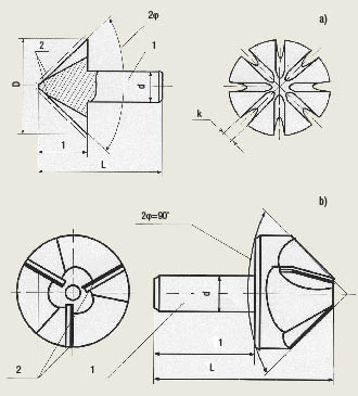
Figure 7: Design of the countersinks: a) single-layer diamond conical countersink, where 1 is the body and 2 is the diamond layer; b) blade-type conical countersink where 1 is the body and 2 is the PCD bonded to a cemented carbide substrate.
Drilling productivity using diamond tools is three to nine times higher, the quality of machined surface is higher and drilling accuracy is two to two-and-a-half times higher compared to standard technology. The degree of hole accuracy for diamond drills depends on the hole diameter. For example, the accuracy is 36μm (0.0014 “) or better for a 2mm (0.08 “) hole, and the accuracy is 116μm (0.0046 “) or better for a 60mm (2.36 “) hole.
Countersinking of PCM is performed to produce conical cavities for rivets. Riveted structures consist of PCM packets, such as carbon plastic and carbon plastic, organic plastic and organic plastic and mixed packets of carbon plastic and an aluminum or titanium alloy. Such PCM packets and metallic PCM are not thicker than 6mm (0.24 “).
Single-layer diamond abrasive and cutting blade-type countersinks have been developed (Figure 7). A cutting blade consists of PCD bonded to a cemented tungsten-carbide substrate. The optimal cutting speed is 3 to 20 m/sec. (590 to 3,940 sfm), the optimal feed rate is 0.01 to 0.12 m/sec. (2.0 to 24.0 sfm), and the optimal DOC is 0.5mm to 5.0mm (0.02 ” to 0.20 “).
Compared to standard HSS and cemented carbide countersinks, single-layer diamond countersinks last seven to eight times longer when used for carbon-based plastics, four to five times longer when used for boron-based plastics and 10 to 12 times longer when countersinking organic plastics. Countersinking productivity is three to five times higher and the quality of the machined surface is better compared to standard technology.
The study of abrasive machining of polymeric composite materials resulted in the development of highly effective tools made of superhard materials and scientifically proven recommendations for their applications. The study also resulted in increased productivity when applying diamond tools to machine PCM and improved surface finishes for PCM parts. CTE
About the Authors: A.A. Shepelev, D.Sc., E.P. Poladko, Ph.D. and B.B. Grzhybovskyi are with the Scientific and Technologic Diamond Concern “ALKON” (Ukraine); V.G. Sorochenko, Ph.D. and A.A. Shepelev Jr. are with the V. N. Bakul Institute for Superhard Materials of the National Academy of Sciences of Ukraine. The article was adapted from one published in Equipment and Tools for Professionals, International Magazine for Metalworking, Issue No. 4, 2008. For more detailed information, please contact “ALKON” via e-mail at alcon2_zakaz@ism.kiev.ua. The article was translated from Russian by Dr. Edmund Isakov, metalcutting consultant and writer.
Glossary terms in this article
Related




Subscribers can use MFGAxis notes, saves and discussion tools with their innoNET account.


