Utilizing Heidenhain’s TNC functions for perfect molds
Utilizing Heidenhain’s TNC functions for perfect molds
Many TNC functions of Heidenhain controls offer possible solutions to the conflicting demands of a production process that is simultaneously precise and efficient. Here is a look at some of those functions.
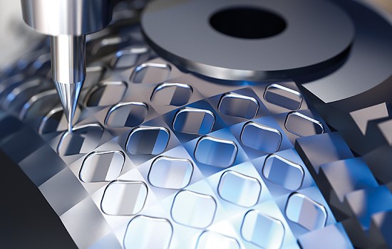
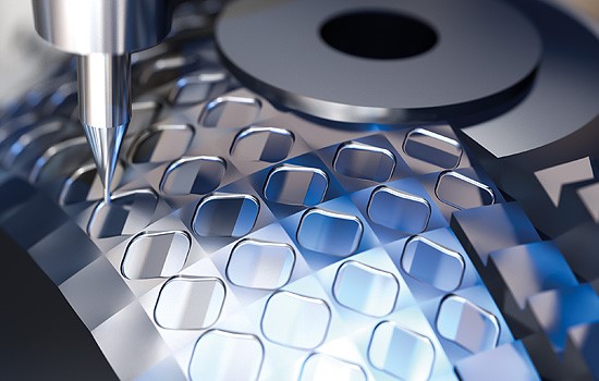 In tool and mold making, dimensional and contour errors need to be so low as to be barely measurable and must never be visible. These requirements, however, are increasingly at odds with demands for higher productivity and lower costs.
Many TNC functions of Heidenhain controls offer possible solutions to the conflicting demands of a production process that is simultaneously precise and efficient. The user can take advantage of these functions that bring out the best of a machine in any machining scenario while meeting workpiece accuracy requirements.
Here is a look at some of those functions.
Tuning a machine to given machining conditions
In Cycle 32 Tolerance, the TNC user can precisely tune the machine setup by adapting the contouring deviation T to the task at hand, thus individually specifying the path width that is available to the control. The user can directly influence the maximum attainable contouring feed rate and also the machining time. This is especially the case for contour elements with numerous changes in direction, which is a common characteristic of free-form surfaces.
Some machine tool builders also offer their own cycles based on Cycle 32. These are often designated Cycle 332. In addition to the contouring deviation T that the TNC user enters, these cycles make further modifications to the machine setup that the OEM had programmed for specific machining operations, such as roughing, finishing or pre-finishing.
The Advanced Dynamic Prediction (ADP) function offers another possibility for optimizing the machining process. It starts with the data quality of the NC program and enables optimized motion control for feed axes in 3- and 5-axis milling. Insufficient data quality frequently causes poor motion control, leading to inferior surface quality of the milled workpieces.
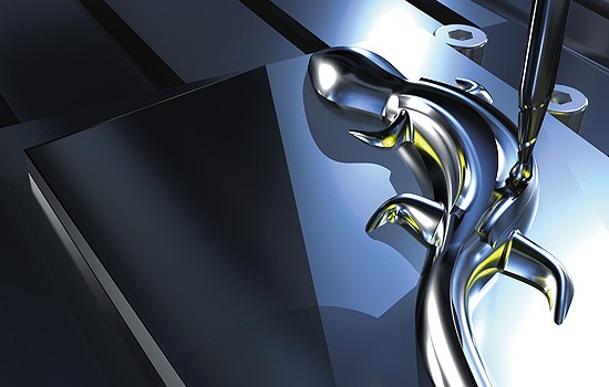 With ADP, the TNC control can dynamically calculate the contour in advance and adapt the axis speeds in time for contour transitions using acceleration-limited and jerk-smoothing motion control. As a result, clean surfaces can be milled in short machining times even for contours with highly irregular point distributions in neighboring tool paths. The strengths of ADP are apparent, for example, in the resulting symmetrical feed behavior on forward and reverse paths during bidirectional finish milling and in the form of particularly smooth feed-rate curves on parallel milling paths.
Take advantage of milling machine dynamics
The dynamic precision package of functions for the TNC controls is a collection of functions that combine high accuracies with dynamic motions. These functions minimize not only forces that affect the mechanics of a machine tool during operation, but also the resulting deviations at the tool center point.
The Cross Compensation (CTC) function compensates for forces that are introduced by dynamic acceleration processes and that briefly deform parts of the machine, leading to deviations at the tool center point. Regardless of the actual acceleration, CTC makes either more precise production with better surfaces possible, or it significantly reduces the machining times by increasing the jerk.
Active Vibration Damping (AVD) suppresses dominant low-frequency vibrations and permits fast, vibration-free milling. This makes it possible to set high-jerk values. Machining times can be reduced without compromising surface quality. In particular, the combination of CTC and AVD helps reconcile the contradictory requirements of accuracy and speed. In practice, this functionality provides greater efficiency during the milling of high-quality, free-form contours.
The Load Adaptive Control (LAC) function continuously determines the current mass for linear axes, or the mass moment of inertia for rotary axes, and adapts the feed-rate control to the values measured at any given time. This improves the dynamic accuracy of the axis for every situation under load, and enables the use of optimized jerk values for the feed axes on the workpiece side. The result is a shorter machining time, because the feed axes reach the desired positions sooner. In addition, LAC compensates for all changed friction values and therefore ensures higher contour accuracy.
Implement a workpiece's accuracy requirements
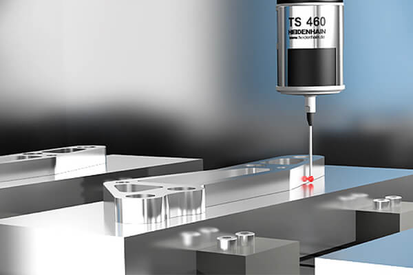 Accuracy requirements are becoming ever more stringent, particularly in the realm of 5-axis machining. Complex parts must be manufactured with both precision and reproducible accuracy, including over extended periods of time. During machining, however, machine components are subjected to relatively high temperature fluctuations. The kinematic transformation chain should therefore be adapted correspondingly. The KinematicsOpt software option handles the recalibration, and saves all data regarding modifications to the kinematic configuration.
A triggering 3-D touch probe is used to measure the position of a precise calibration sphere at various rotary axis settings. The result is a report providing the current actual accuracy during tilting. If desired, KinematicsOpt also automatically optimizes the measured axes simultaneously, and requisite modifications to the machine data are also automatically implemented. The user needs no detailed knowledge about the kinematic configuration of the machine and can recalibrate his milling machine in just a few minutes. If the calibration sphere is permanently mounted on the machine table, then this procedure can even be performed as an automated step between the individual machining processes.
Radius cutters whose geometry deviates from the ideal circular shape also negatively affect the machining result, since the contact point of the cutter radius with the workpiece as calculated by the control does not match the value for that of the actual radius.
The 3D-ToolComp option and touch probe Cycle 444 together are a powerful method for three-dimensional tool radius compensation. A compensation table enables the specification of angle-dependent delta values that describe this deviation. The TNC control uses this data to compensate for the radius value defined at the current tool contact point on the workpiece.
For the contact point to be determined with precision, the NC program must be generated with surface-normal blocks (LN blocks) by the CAM system. These surface-normal blocks define the tool position and the contact point on the workpiece, and optionally specify the tool orientation relative to the workpiece surface.
Plan and monitor automated production with ease
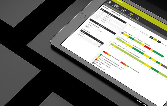 If the machine tool provides perfect machining results, then the associated processes should also run in an optimized manner. Intelligently networked systems for job planning, job management, and job monitoring should provide a comprehensive view of job lists, running processes, work progress, and any necessary interventions.
Batch Process Manager organizes pending jobs clearly and in a logical manner. To accomplish this, the user creates a lineup of jobs directly on the Heidenhain control. These might be jobs for the approaching night shift, for an entire day, or for the upcoming weekend. Batch Process Manager checks this job list and provides important information prior to machining, such as when manual interventions will be necessary and how long the machine will be utilized. Batch Process Manager thereby allows for precise planning of the machining sequence and facilitates the smooth execution of pending jobs.
The StateMonitor software gives a fast, real-time overview of the current machine and job statuses for all connected machines. This monitoring software enables machine data acquisition (MDA) and provides information about machine messages. The user thereby maintains an overview of his machine tools and jobs at all times. The user can access StateMonitor from any device featuring an up-to-date web browser, meaning not only PCs, smartphones, and tablets but also, of course, controls from Heidenhain and Extended Workspace.
For more information on these functions and Heidenhain controls, visit www.heidenhain.us.


