In last month’s column, I noted chip thinning is one of the key concepts programmers and machinists should understand. Presented here is further discussion about how chip thinning can enhance productivity.
Chip thinning, at first glance, can be a daunting concept to grasp because it involves complex geometric relationships and intimidating calculations. This often causes machinists and programmers to avoid learning how to take advantage of the concept.
All images courtesy Savannah Machinery Works
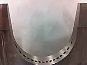
Figure 1. A portion of a challenging part at Savannah Machinery Works.
A good programmer will typically calculate the spindle speed using a published formula, such as sfm ÷ tool diameter × 3.82, and then use the rpm to calculate the feed rate, using the equation rpm × number of flutes × chip load per flute. This tried-and-true method is certainly acceptable and usually provides adequate machining performance. Once completed, a program typically goes to the shop floor and a machinist adjusts the speed and feed to achieve the desired results.
Having a good starting point for the speed and feed is critical to success in any machining operation and a knowledgeable programmer can usually get close on the first try. But there are times when the setup does not provide the necessary rigidity to support conventional methods, the part geometry makes conventional machining techniques a challenge or the workpiece material is difficult to machine. These scenarios can cause chatter, tool breakage, part movement and poor surface finish.
The first reaction of experienced machinists to these problems is to reduce the speed, feed or both. Slowing the operation is not necessarily wrong but it increases cycle time.
Understanding how to take advantage of chip thinning can counter the learned response of reducing cutting parameters to combat difficult situations. The major cutting tool manufacturers publish chip thinning calculations in their technical literature and some have simplified the calculations into tabular form based on the ratio of tool diameter to DOC. Nonetheless, chip thinning can be tedious to apply when dealing with numerous or complex toolpaths.
The advantages of chip thinning are so great that several CAM developers offer software packages that capitalize on its application. But it is possible to take advantage of chip thinning without expensive software if programmers and machinists understand the concept and approach it creatively.
Figure 1 on page 38 shows a portion of one of Savannah Machinery Works’ more challenging parts. Although the shape is not complex, the tolerances are not tight and the material is only moderately difficult to machine, it was difficult to achieve the desired results with conventional machining.
Figure 2 shows how a 12mm-dia., 4-flute, carbide endmill initially entered from outside the pocket, moved to the middle and began a canned pocketing routine. This method caused chip packing in the flutes, flute chipping and part movement in the chuck. Our first response was to reduce the cutting speed and feed rate to overcome these issues, resulting in an agonizingly long cycle time.
The second and successful solution was to alter the toolpath so it mimics a trochoidial path, which takes advantage of chip thinning. I did not have the software necessary to produce a true trochoidial path, so I improvised by creating a toolpath with a semicircular shape. This path was then copied several times with a 0.5mm shift between each path, giving me a 0.5mm radial engagement (Figure 3).
Once the tool was positioned in the pocket, I programmed a canned pocketing routine using the same cutting parameters as the entry path but changed the radial step-over from the original 4mm to 0.5mm (Figure 4).
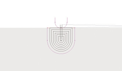
Figure 2. Cutting parameters when performing a canned pocketing routine with a 12mm-dia., 4-flute, carbide endmill: 1,250 rpm, 250 mm/min. and 4.0mm radial step-over in the pocket. Roughing consumed 6 minutes and 33 seconds, and finishing took 38 seconds.
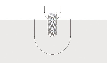
Figure 3. Cutting parameters for the entry toolpath when performing chip thinning with a 12mm-dia., 4-flute, carbide endmill: 3,000 rpm, 2,000 mm/min. and 0.5mm radial DOC. Entry time was 55 seconds.
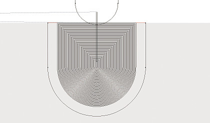
Figure 4. Cutting parameters for the pocketing routine when performing chip thinning with a 12mm-dia., 4-flute, carbide endmill: 3,000 rpm, 2,000 mm/min. and 0.5mm radial step-over. Finishing the pocket took 5 minutes and 17 seconds.
By entering the part using a shallow DOC, I reduced the tool pressure, volume of heat transferred into the part and chip size. A reduction in tool pressure typically minimizes part movement. Less heat into the part reduces the tendency of chip welding. And smaller chips are easier to evacuate from the cutting zone, minimizing chip packing.
The tool also didn’t experience flute chipping, which minimizes tool regrinding during reconditioning, and part movement was eliminated, which avoids scrap or rework. In addition, the cycle time was 21 seconds less—a bonus.
Because I did not have access to high-performance milling software, I derived the cutting speeds at the machine control while observing the process. In short, it is not necessary to have such software or perform tedious calculations to take advantage of chip thinning.
It’s a good idea, though, to have a cutting tool supplier present a short class to teach operators some of the basic calculations. Once the basic concept is understood, go to the machine and run some test cuts by programming different toolpaths and altering combinations of the cutting speed, feed rate and DOC. These tests can be fun; I’ve had a shop full of machinists watching chips flying wildly inside the machine while I tested the limits of an endmill. CTE
About the Author: Christopher Tate is manufacturing engineering lead for machining at Mitsubishi Power Systems, Savannah (Ga.) Machinery Works, a global builder of gas and steam turbines. He has 19 years of experience in the metalworking industry and holds a Master of Science and Bachelor of Science from Mississippi State University. E-mail: [email protected].
Related Glossary Terms
- chatter
chatter
Condition of vibration involving the machine, workpiece and cutting tool. Once this condition arises, it is often self-sustaining until the problem is corrected. Chatter can be identified when lines or grooves appear at regular intervals in the workpiece. These lines or grooves are caused by the teeth of the cutter as they vibrate in and out of the workpiece and their spacing depends on the frequency of vibration.
- chuck
chuck
Workholding device that affixes to a mill, lathe or drill-press spindle. It holds a tool or workpiece by one end, allowing it to be rotated. May also be fitted to the machine table to hold a workpiece. Two or more adjustable jaws actually hold the tool or part. May be actuated manually, pneumatically, hydraulically or electrically. See collet.
- computer-aided manufacturing ( CAM)
computer-aided manufacturing ( CAM)
Use of computers to control machining and manufacturing processes.
- cutting speed
cutting speed
Tangential velocity on the surface of the tool or workpiece at the cutting interface. The formula for cutting speed (sfm) is tool diameter 5 0.26 5 spindle speed (rpm). The formula for feed per tooth (fpt) is table feed (ipm)/number of flutes/spindle speed (rpm). The formula for spindle speed (rpm) is cutting speed (sfm) 5 3.82/tool diameter. The formula for table feed (ipm) is feed per tooth (ftp) 5 number of tool flutes 5 spindle speed (rpm).
- endmill
endmill
Milling cutter held by its shank that cuts on its periphery and, if so configured, on its free end. Takes a variety of shapes (single- and double-end, roughing, ballnose and cup-end) and sizes (stub, medium, long and extra-long). Also comes with differing numbers of flutes.
- feed
feed
Rate of change of position of the tool as a whole, relative to the workpiece while cutting.
- flutes
flutes
Grooves and spaces in the body of a tool that permit chip removal from, and cutting-fluid application to, the point of cut.
- gang cutting ( milling)
gang cutting ( milling)
Machining with several cutters mounted on a single arbor, generally for simultaneous cutting.
- metalworking
metalworking
Any manufacturing process in which metal is processed or machined such that the workpiece is given a new shape. Broadly defined, the term includes processes such as design and layout, heat-treating, material handling and inspection.
- milling
milling
Machining operation in which metal or other material is removed by applying power to a rotating cutter. In vertical milling, the cutting tool is mounted vertically on the spindle. In horizontal milling, the cutting tool is mounted horizontally, either directly on the spindle or on an arbor. Horizontal milling is further broken down into conventional milling, where the cutter rotates opposite the direction of feed, or “up” into the workpiece; and climb milling, where the cutter rotates in the direction of feed, or “down” into the workpiece. Milling operations include plane or surface milling, endmilling, facemilling, angle milling, form milling and profiling.
- step-over
step-over
Distance between the passes of the toolpath; the path spacing. The distance the tool will move horizontally when making the next pass. Too great of a step-over will cause difficulty machining because there will be too much pressure on the tool as it is trying to cut with too much of its surface area.
- toolpath( cutter path)
toolpath( cutter path)
2-D or 3-D path generated by program code or a CAM system and followed by tool when machining a part.
Author

Christopher Tate is the owner of Tate Engineering, a Natchez, Mississippi, firm that helps manufacturers solve efficiency problems. Tate, who earned master's degree in industrial technology from Mississippi State University, has 32 years of experience in the metalworking industry.


