Originally designed to efficiently process long, slender parts for the watchmaking industry, Swiss-style lathes have evolved. The general concept of what it means for a machine to be “Swiss,” however, hasn’t changed much. To qualify for that categorization, a machine must have a sliding headstock and guide bushing. As the headstock moves, it feeds the bar stock past cutting tools, which remain close to the bushing support. However, modifications to Swiss-style machines have opened up new opportunities for the production of more complex parts more rapidly than ever before.
The Cincom L20X has the capacity to mount 39 cutting tools.
So what’s new in Swiss-style machine tool design? In a word, “more.” There are more tools and tooling options, axes, high-pressure cutting fluid options and more-powerful CNCs. The machines have evolved to offer more because of the demands of the industries they support, including medical, aerospace and electronics.
Slide and GuideThe sliding headstock and guide bushing at the heart of Swiss-style machining provide a uniquely rigid setup ideal for complex, high-precision parts and parts with length-to-diameter ratios above what is possible—10:1 and beyond—on conventional lathes. Parts made on these machines are typically less than 32mm (1.26") in diameter.
Swiss-style machines are as complex as the workpieces they make. Many are equipped with 11 or more axes, subspindles, driven tools and a variety of cutting tools. This complexity and the technology that supports it continues to advance.
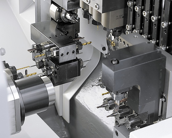
More tools in the machine means more options for complex jobs. The evolution of Swiss-style machines has been driven primarily by adding cutting tool positions. Most of the increase has come in the form of driven, or live, tools. These tools may point toward the main spindle, the subspindle or both, and be oriented in either the axial or radial position. The proliferation of driven tools enables more milling options and, when coupled with additional axes, the machining options seem nearly endless.
To see how the number of tools available in a machine has increased, examine the changes Marubeni Citizen-Cincom Inc. has made to its L-series machines. The L20 Type VII, first built in 2001, had a total of 16 tool stations. Six turning tools and four live tools were oriented in the cross-drilling direction for work on the main spindle, three ID tool stations were on the back slide positioned for work on the main spindle, and three more tooling stations were positioned for ID work on the subspindle.
The model is no longer being built. Instead, other options exist, including the L20 Type X, which holds up to 39 tools. The Type X has many more tooling variations, with 14 different tooling attachments for the six tool positions on the opposite tool post and eight for the back tool post, most involving driven tools for simultaneous machining on both spindles in radial and axial positions.
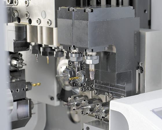
This tool group is used for work on the subspindle of the L20X.
Driven tools have been placed on the subspindle slide as well. What makes this even more significant is the addition of a Y-axis on the back slide. Driven tools have long been available on the main slide, but not on the subspindle. This additional capability on the Y-axis adds flexibility through the capacity to mill in three axes. More importantly, it also allows a programmer the option of balanced, or pinch, milling, where two tools simultaneously work on the same workpiece to remove material faster.
Balanced machining is not new. Pinch turning has long been used on Swiss-style machines to allow two tools to cut bar stock to finished dimensions—one to cut an intermediate diameter and another to finish. Both tools cut simultaneously, with the finishing tool following a little behind the roughing insert.
The technique does the same thing for milling, but with a slight difference. Two tools milling on opposite sides of the workpiece balance the cutting forces, thus significantly reducing the natural tendency of the workpiece to deflect.
Not Just More ToolsMore tools aren’t the only enhancement. Newer Swiss-style machines provide flexibility through the use of modular tools or tooling adapters. These adapters include milling spindles, which the machine operator can quickly change; as a result, newer Swiss-style machines have many more options than their predecessors. The entire tooling configuration of the machine can be altered in a matter of minutes by removing one radial live tool and replacing it with a 3-spindle unit.
Live tools typically work only on the main spindle and are oriented only in the radial direction. In the past, this meant that all milling had to be done on the main spindle, which often reduced how much simultaneous work could be done on a given part. With two spindles, the goal is always to balance the work so neither spindle waits long for the other to finish. A part requiring little turning but needing many cross-holes and milled slots might not ever see any simultaneous work. With the options provided by modular tooling, more of the milling can be transferred to the subspindle, thereby radically reducing cycle time.
One way to add flexibility to driven tools is a modular tool option that allows the operator to quickly change the orientation of one set of driven tools from the axial position to the radial and back in less than 10 minutes. Depending on the workpiece, live tools can be swapped to accommodate those changes.
B Changing on the FlyModularity allows a machine to be transformed, but only during setup. To allow this transformation to occur on the fly requires the addition of a B-axis, a rotary axis that moves the spindle orientation in relationship to the main spindle within a total range of 105°.
The B-axis adds capability in a couple of critical ways. With a B-axis, one milling cutter can act as both a facemill and a cross mill. This adds an extra tool to the mix without dedicating an additional station, which adds one more orientation. The B-axis can also continuously change the cutting angle, allowing the programming of slanted holes at a number of angles or contouring with simultaneous 4-axis control when utilizing the C-axis of the spindle.
Added PressureThe use of high-pressure fluids has become a staple of Swiss-style machining. These add-on and often aftermarket units help control the flow of chips when turning, directing long, stringy chips from the cutting zone or even breaking them into more smaller, more manageable pieces. High-pressure coolant is beneficial in any drilling operation that calls for holes deeper than 5 times diameter. High-pressure coolant also is commonly applied to flush chips out of the subspindle.
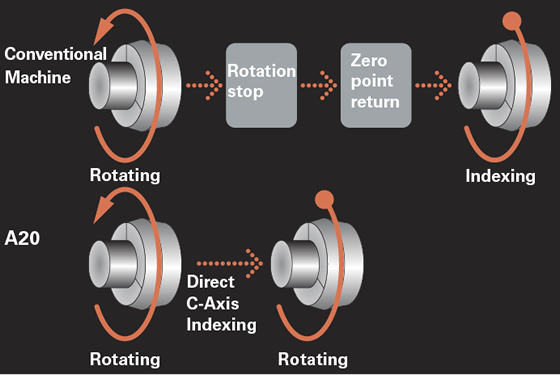
When indexing the C-axis on the Cincom A20 (below), it is not necessary to wait for the spindle to stop first and then orient to zero. The spindle can directly index to the programmed position.
With machine builders adding tool stations and additional axes, additional programmable high-pressure lines are required to direct the cutting fluid where and when it is needed. In the past, it might have been enough to have these units control four lines to the tools, but with more tools being added to Swiss-style machines, this seems woefully inadequate. Eight or 10 lines are now more common.
It is not enough to simply plumb high-pressure cutting fluid to a nozzle near the cutting edge. Any Swiss-style machine operator will complain that far too much time is spent cutting, bending and fitting steel tubing to achieve the desired output of the high-pressure unit. Many tooling manufacturers are seeking solutions that plumb coolant to the cutting zone through the tool shank or through clamps holding the tool. The latter seeks to reduce setup time by eliminating the need to disconnect high-pressure lines.
More Computing PowerAnother trend in Swiss-style machines is the reduced size and increased speed of microprocessors. Anywhere a microprocessor is used, more computing power runs more sophisticated algorithms to better monitor faster servos. In the case of Swiss-style machines, it also means coordinating the growing number of axes.
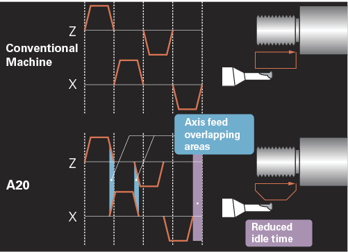
Axis-feed motion overlap on the A20 reduces cycle time by allowing the motion of one axis to be completed while the motion of the next axis begins, as this threading example shows.
It is never just one innovation in technology that defines the advances in machine tool technology. As stated earlier, the basic design of Swiss-style machines has not drastically changed. The concept is still based on a sliding headstock and guide bushing. Changes in machine design are often small, incremental and dependent on other technologies. Machine controls must be faster, more accurate and respond more smoothly to directional changes to the axes. These demands require faster communication between the encoder and the servo amplifier. To achieve this, many control manufacturers use Ethernet connections to reach the required communication speeds and capture signals coming from the encoders.
Already high feed rates continue to increase, but this is only one metric to consider. Acceleration rates might not allow the axes to reach 30.48 to 44.96 m/min. (1,200 to 1,770 ipm). Considering that most Swiss-style machines utilize gang-style tooling, a tool change might consist of a 25.4mm (1") movement to index from one tool to the next in the rack. With a tool change consuming less than a second, a 20 percent reduction in chip-to-chip time may only remove 160 milliseconds per tool change.
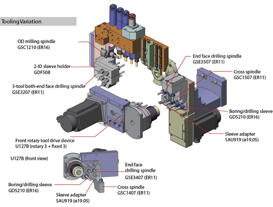
The variety of tooling options on newer Swiss-style machines, such as this L20X, gives the machines their ability to machine more complex parts.
Faster rapids are one thing, but acceleration has, perhaps, never been more important than in machines with shorter distances to travel—such as Swiss-style machines. Over the years, many innovations have reduced that acceleration rate during rapid-traverse motions. With the control monitoring the torque and position of the axes at higher encoder resolutions, the acceleration curve is improved, often reducing the time needed to reach the maximum feed rate. This can reduce the noncutting portion of cycle times by up to 30 percent.
Significant changes may occur in other areas as well. For example, spindle orientation time can be reduced by the ability of advanced controls to position the C-axis using maximum torque, which is made possible through the higher speeds and higher resolution of encoders used in high-end servos.
More for Your MoneyOf course, having more of anything suggests paying more to get it. However, this seemingly logical assumption is not always true. More powerful microprocessors and larger data storage options are available at the same price as their 10-year-old predecessors. Similar to consumer electronics, this concept of more computing power per dollar spent exists in Swiss-style machines.
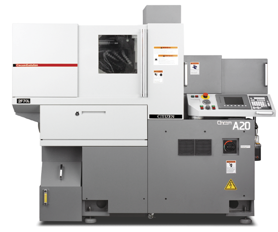
Compare the Citizen L-series of 12 years ago with a new A-series machine similarly configured. The base price difference between these machines would be about $40,000, with the A20 being the less-expensive option, even without adjusting for inflation. Make no mistake, these two machines are not really the same. They have similar tooling configurations, but the A20 has the benefit of a faster control to produce a part about 30 percent faster. As the ads for AT&T Wireless say, more really is better. CTE
Related Glossary Terms
- bushing
bushing
Cylindrical sleeve, typically made from high-grade tool steel, inserted into a jig fixture to guide cutting tools. There are three main types: renewable, used in liners that in turn are installed in the jig; press-fit, installed directly in the jig for short production runs; and liner (or master), installed permanently in a jig to receive renewable bushing.
- coolant
coolant
Fluid that reduces temperature buildup at the tool/workpiece interface during machining. Normally takes the form of a liquid such as soluble or chemical mixtures (semisynthetic, synthetic) but can be pressurized air or other gas. Because of water’s ability to absorb great quantities of heat, it is widely used as a coolant and vehicle for various cutting compounds, with the water-to-compound ratio varying with the machining task. See cutting fluid; semisynthetic cutting fluid; soluble-oil cutting fluid; synthetic cutting fluid.
- cutting fluid
cutting fluid
Liquid used to improve workpiece machinability, enhance tool life, flush out chips and machining debris, and cool the workpiece and tool. Three basic types are: straight oils; soluble oils, which emulsify in water; and synthetic fluids, which are water-based chemical solutions having no oil. See coolant; semisynthetic cutting fluid; soluble-oil cutting fluid; synthetic cutting fluid.
- facemill
facemill
Milling cutter for cutting flat surfaces.
- feed
feed
Rate of change of position of the tool as a whole, relative to the workpiece while cutting.
- finishing tool
finishing tool
Tool, belt, wheel or other cutting implement that completes the final, precision machining step/cut on a workpiece. Often takes the form of a grinding, honing, lapping or polishing tool. See roughing cutter.
- gang cutting ( milling)
gang cutting ( milling)
Machining with several cutters mounted on a single arbor, generally for simultaneous cutting.
- inner diameter ( ID)
inner diameter ( ID)
Dimension that defines the inside diameter of a cavity or hole. See OD, outer diameter.
- milling
milling
Machining operation in which metal or other material is removed by applying power to a rotating cutter. In vertical milling, the cutting tool is mounted vertically on the spindle. In horizontal milling, the cutting tool is mounted horizontally, either directly on the spindle or on an arbor. Horizontal milling is further broken down into conventional milling, where the cutter rotates opposite the direction of feed, or “up” into the workpiece; and climb milling, where the cutter rotates in the direction of feed, or “down” into the workpiece. Milling operations include plane or surface milling, endmilling, facemilling, angle milling, form milling and profiling.
- milling cutter
milling cutter
Loosely, any milling tool. Horizontal cutters take the form of plain milling cutters, plain spiral-tooth cutters, helical cutters, side-milling cutters, staggered-tooth side-milling cutters, facemilling cutters, angular cutters, double-angle cutters, convex and concave form-milling cutters, straddle-sprocket cutters, spur-gear cutters, corner-rounding cutters and slitting saws. Vertical cutters use shank-mounted cutting tools, including endmills, T-slot cutters, Woodruff keyseat cutters and dovetail cutters; these may also be used on horizontal mills. See milling.
- milling machine ( mill)
milling machine ( mill)
Runs endmills and arbor-mounted milling cutters. Features include a head with a spindle that drives the cutters; a column, knee and table that provide motion in the three Cartesian axes; and a base that supports the components and houses the cutting-fluid pump and reservoir. The work is mounted on the table and fed into the rotating cutter or endmill to accomplish the milling steps; vertical milling machines also feed endmills into the work by means of a spindle-mounted quill. Models range from small manual machines to big bed-type and duplex mills. All take one of three basic forms: vertical, horizontal or convertible horizontal/vertical. Vertical machines may be knee-type (the table is mounted on a knee that can be elevated) or bed-type (the table is securely supported and only moves horizontally). In general, horizontal machines are bigger and more powerful, while vertical machines are lighter but more versatile and easier to set up and operate.
- modular tooling
modular tooling
1. Tooling system comprised of standardized tools and toolholders. 2. Devices that allow rapid mounting and replacement of tools. Commonly used with carousel toolchangers and other computerized machining operations. See toolchanger; toolholder.
- shank
shank
Main body of a tool; the portion of a drill or similar end-held tool that fits into a collet, chuck or similar mounting device.
- threading
threading
Process of both external (e.g., thread milling) and internal (e.g., tapping, thread milling) cutting, turning and rolling of threads into particular material. Standardized specifications are available to determine the desired results of the threading process. Numerous thread-series designations are written for specific applications. Threading often is performed on a lathe. Specifications such as thread height are critical in determining the strength of the threads. The material used is taken into consideration in determining the expected results of any particular application for that threaded piece. In external threading, a calculated depth is required as well as a particular angle to the cut. To perform internal threading, the exact diameter to bore the hole is critical before threading. The threads are distinguished from one another by the amount of tolerance and/or allowance that is specified. See turning.
- turning
turning
Workpiece is held in a chuck, mounted on a face plate or secured between centers and rotated while a cutting tool, normally a single-point tool, is fed into it along its periphery or across its end or face. Takes the form of straight turning (cutting along the periphery of the workpiece); taper turning (creating a taper); step turning (turning different-size diameters on the same work); chamfering (beveling an edge or shoulder); facing (cutting on an end); turning threads (usually external but can be internal); roughing (high-volume metal removal); and finishing (final light cuts). Performed on lathes, turning centers, chucking machines, automatic screw machines and similar machines.
Author

Don Nelson served as publisher of Cutting Tool Engineering from January 2001 through May 2018.
 ARTICLES