All images courtesy Makino
What are the most difficult titanium alloys to machine and why?
Part manufacturers often complain about Ti5Al5Mo5V3Cr (Ti5553) and Ti10V2Fe3Al (Ti1023). This is because these alloys are closer to the beta state than others, and, therefore, have an even higher strength. However, the real challenge is that because Ti6Al4V (Ti64) dominates so much of the market, any other alloy creates a challenge because people don’t have comprehensive data or experience to guide them through the machining process. This can cause a lot of growing pains.
What occurs at the tool/workpiece interface when machining titanium?Orthopedic medical plates.
The tool/workpiece interface is a truly fascinating area when cutting titanium. Because titanium has a low modulus of elasticity, the first reaction is for the material to push away from the cutting tool. A sharp tool should be applied to reduce the cutting forces and begin slicing through the material. A small tool/chip interface exists where, for a distance measured in thousandths of an inch, the material is in direct contact with the tool rake face. This small edge of the tool gets quite hot from all the energy used to deform the material and the friction of the material sliding up the rake face. In addition, the direct contact between the workpiece material and tool reduces the effect of coolant.
What machine tool features are required for effectively cutting titanium alloys, such as the types of construction characteristics that enhance machine rigidity?
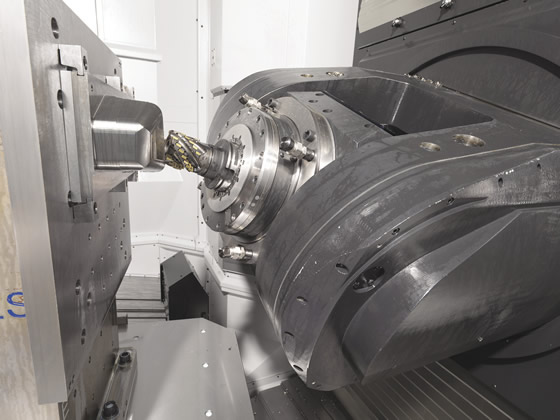
Because titanium is hard, chips don’t effectively carry away heat, so low-rpm cutting parameters work best. Users compensate for this limitation by increasing the axial engagement. This exerts a lot of force on the tool, which requires a rigid toolholder interface and high-torque spindle. Makino recommends the HSK interface when machining titanium: HSK 63 for small machines, HSK 100 for medium-sized ones and HSK 125 for the largest units. Makino’s large T4 and T2 machines have 1,000-Nm spindles that not only supply the torque needed to cut titanium but also provide 52-gpm, 1,000-psi through-spindle coolant to remove the heat. Behind those spindles is a kinematic structure that runs on large box ways. Box ways are still the best method for supporting high cutting forces and, when combined with the Active Damping System, not only provide a rigid structure but also adjust frictional forces based on low-frequency vibration sensing to avoid chatter and cutter damage resulting from structure resonance in real time.
What’s needed to control the temperature at the arc of engagement/are of contact and what does that control enable?
Cutting temperature is primarily driven by cutting speed (rpm), radial engagement and coolant. It is up to the programmer to select the cutting speed and radial engagement to optimize productivity and tool life, but the machine configuration primarily controls the influence of coolant. In addition to high-pressure coolant, machines need high coolant flow. The high pressure is required to penetrate deep into the tool/chip interface and cool the tool at its tip. However, milling tools for cutting titanium often have lots of coolant ports. If the coolant pump doesn’t have the flow capabilities to maintain the pressure through all of the coolant ports, tool life will diminish. When part manufacturers satisfy the tool’s need for coolant with high pressure and high flow, they can achieve massive productivity gains by increasing the surface speed and radial engagement while extending tool life. Water-based coolants are still the most effective at managing the impact of the heat generated when cutting titanium.
The rigidity of the T2 5-axis machining center enables Patriot Machine Inc., St. Charles, Mo., to apply long tools and pursue complex machining processes when cutting titanium, according to Makino.
When enhancing cutting tool security by reducing thermal cracking and overcoming the seizing tendency, what are the tool geometry, substrate and coating requirements?
For titanium, apply a sharp tool with a large primary and secondary relief. This reduces cutting forces and prevents tool adhesion to the springy material. However, this means a very sharp, thin cutting edge machines a hard material with heat issues. Therefore, it is critical to select a carbide grade with good toughness and high hot hardness. The jury is still out on coatings. Positive results are achieved with and without coatings. However, my personal preference is to always start a job with coated tools, simply because it is easier to monitor tool wear. I generally stop using a tool when there is 0.010 " to 0.012 " (0.254mm to 0.305mm) of flank wear. It can be difficult to monitor a wear band that small on an uncoated tool.
What toolpaths promote long tool life, reduce cutting forces and boost productivity when cutting titanium?
Surface speed and radial engagement are the biggest factors impacting tool life. Surface speed is typically constant but radial engagement can vary depending on the CAM software. High-speed milling paths work great in titanium because they allow the user to set a radial engagement and improve tool life and the predictability of the process.
How can vibration be damped to avoid chatter and cutter damage from structure resonance?
On big inserted cutters, users are limited to the machine structure’s ability to dampen the energy from the cut. However, with endmills, it is possible to improve the system’s damping characteristics by using a milling chuck or collet system. These systems have many different pieces, and the interface between each piece creates a place for friction to dampen the vibration. The opposite occurs with a shrink-fit toolholder. Because a shrink-fit holder is one piece, it tends to act like a tuning fork, vibrating for a long time from the impact of machining.
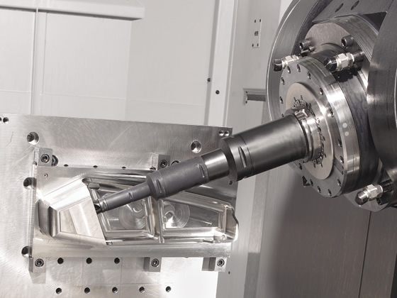
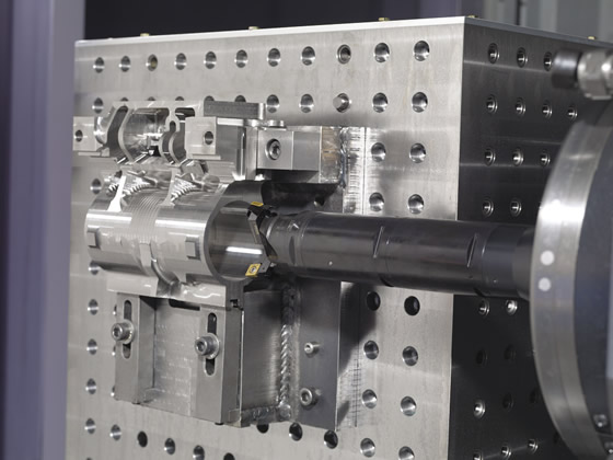
The rigidity and damping capability of Makino’s T-Series machines enable efficiently accessing difficult-to-reach features, according to the company.
When machining large titanium parts, what does removing a majority of the material achieve and what are the challenges when producing those parts?
Forging and processing titanium can be expensive, so it can be cheaper to make even a large part out of a solid piece of titanium. Also, forging and forming titanium can leave strong internal stresses that will come out during machining. This is evident when a part springs away from the locators when it’s unclamped. Yet, when machining a part from a large workpiece, part manufacturers must deal with the typical low metal-removal rates. Increasing roughing rates from 100 to 300 percent is where large-taper spindles with high-torque and high-pressure/high-flow coolant capabilities really shine compared to standard small-taper machines.
How can end users avoid crashes and other accidents to minimize scrap and equipment repairs when cutting these alloys?
First, program stable toolpaths with constant radial and axial engagements. Toolpaths that vary the tool engagement may unexpectedly chip inserts or begin to chatter. Next, control what is happening in the machine by using verification software. Makino, for example, offers a capability called Collision Safe Guard, where the control simulates the program just a few seconds ahead of the actual machining program and checks for crash points or unintended interference. This kind of protection is critical to protect expensive tools, fixtures and, of course, those pricey titanium parts.
What R&D areas are being emphasized to more effectively machine titanium?
Many R&D efforts have involved assembling the best from each part of the machine process. The Makino Titanium Process R&D Center, for instance, works on combining the best machine technologies found in the company’s 5-axis machines with evolutions in toolpath creation, tool design, and coolant type and application. The center continually tests new cutting tools and supporting technologies to develop the most-effective processes. Profitably machining titanium requires a careful analysis of each of these four areas. A mistake in any one can generate scrap parts and diminish machining productivity and tool life. After understanding all of the elements for successful titanium machining, many shops find themselves saying, “Remember when machining titanium was hard?” CTE
Related Glossary Terms
- alloys
alloys
Substances having metallic properties and being composed of two or more chemical elements of which at least one is a metal.
- bandsaw blade ( band)
bandsaw blade ( band)
Endless band, normally with serrated teeth, that serves as the cutting tool for cutoff or contour band machines.
- chatter
chatter
Condition of vibration involving the machine, workpiece and cutting tool. Once this condition arises, it is often self-sustaining until the problem is corrected. Chatter can be identified when lines or grooves appear at regular intervals in the workpiece. These lines or grooves are caused by the teeth of the cutter as they vibrate in and out of the workpiece and their spacing depends on the frequency of vibration.
- chuck
chuck
Workholding device that affixes to a mill, lathe or drill-press spindle. It holds a tool or workpiece by one end, allowing it to be rotated. May also be fitted to the machine table to hold a workpiece. Two or more adjustable jaws actually hold the tool or part. May be actuated manually, pneumatically, hydraulically or electrically. See collet.
- coated tools
coated tools
Carbide and high-speed-steel tools coated with thin layers of aluminum oxide, titanium carbide, titanium nitride, hafnium nitride or other compounds. Coating improves a tool’s resistance to wear, allows higher machining speeds and imparts better finishes. See CVD, chemical vapor deposition; PVD, physical vapor deposition.
- collet
collet
Flexible-sided device that secures a tool or workpiece. Similar in function to a chuck, but can accommodate only a narrow size range. Typically provides greater gripping force and precision than a chuck. See chuck.
- computer-aided manufacturing ( CAM)
computer-aided manufacturing ( CAM)
Use of computers to control machining and manufacturing processes.
- coolant
coolant
Fluid that reduces temperature buildup at the tool/workpiece interface during machining. Normally takes the form of a liquid such as soluble or chemical mixtures (semisynthetic, synthetic) but can be pressurized air or other gas. Because of water’s ability to absorb great quantities of heat, it is widely used as a coolant and vehicle for various cutting compounds, with the water-to-compound ratio varying with the machining task. See cutting fluid; semisynthetic cutting fluid; soluble-oil cutting fluid; synthetic cutting fluid.
- cutting speed
cutting speed
Tangential velocity on the surface of the tool or workpiece at the cutting interface. The formula for cutting speed (sfm) is tool diameter 5 0.26 5 spindle speed (rpm). The formula for feed per tooth (fpt) is table feed (ipm)/number of flutes/spindle speed (rpm). The formula for spindle speed (rpm) is cutting speed (sfm) 5 3.82/tool diameter. The formula for table feed (ipm) is feed per tooth (ftp) 5 number of tool flutes 5 spindle speed (rpm).
- flank wear
flank wear
Reduction in clearance on the tool’s flank caused by contact with the workpiece. Ultimately causes tool failure.
- gang cutting ( milling)
gang cutting ( milling)
Machining with several cutters mounted on a single arbor, generally for simultaneous cutting.
- hardness
hardness
Hardness is a measure of the resistance of a material to surface indentation or abrasion. There is no absolute scale for hardness. In order to express hardness quantitatively, each type of test has its own scale, which defines hardness. Indentation hardness obtained through static methods is measured by Brinell, Rockwell, Vickers and Knoop tests. Hardness without indentation is measured by a dynamic method, known as the Scleroscope test.
- machining center
machining center
CNC machine tool capable of drilling, reaming, tapping, milling and boring. Normally comes with an automatic toolchanger. See automatic toolchanger.
- milling
milling
Machining operation in which metal or other material is removed by applying power to a rotating cutter. In vertical milling, the cutting tool is mounted vertically on the spindle. In horizontal milling, the cutting tool is mounted horizontally, either directly on the spindle or on an arbor. Horizontal milling is further broken down into conventional milling, where the cutter rotates opposite the direction of feed, or “up” into the workpiece; and climb milling, where the cutter rotates in the direction of feed, or “down” into the workpiece. Milling operations include plane or surface milling, endmilling, facemilling, angle milling, form milling and profiling.
- modulus of elasticity
modulus of elasticity
Measure of rigidity or stiffness of a metal, defined as a ratio of stress, below the proportional limit, to the corresponding strain. Also known as Young’s modulus.
- rake
rake
Angle of inclination between the face of the cutting tool and the workpiece. If the face of the tool lies in a plane through the axis of the workpiece, the tool is said to have a neutral, or zero, rake. If the inclination of the tool face makes the cutting edge more acute than when the rake angle is zero, the rake is positive. If the inclination of the tool face makes the cutting edge less acute or more blunt than when the rake angle is zero, the rake is negative.
- relief
relief
Space provided behind the cutting edges to prevent rubbing. Sometimes called primary relief. Secondary relief provides additional space behind primary relief. Relief on end teeth is axial relief; relief on side teeth is peripheral relief.
- toolholder
toolholder
Secures a cutting tool during a machining operation. Basic types include block, cartridge, chuck, collet, fixed, modular, quick-change and rotating.
- toolpath( cutter path)
toolpath( cutter path)
2-D or 3-D path generated by program code or a CAM system and followed by tool when machining a part.