When executives at Murata Machinery Ltd. approached researchers at Nagoya University in Japan about chip-jamming issues in the machine tool builder’s turning equipment, it started an interesting dialogue between industry and academia. Chips were jamming, causing downtime and a hazardous environment for the operators.
“Although the use of chipbreakers is the long-standing rule in high-performance turning, chips from high-ductile material and thin chips produced in finishing operations can’t be broken reliably with chipbreakers,” said Dr. Burak Sencer, assistant professor, mechanical engineering, at Oregon State University, who worked with the team in Japan.
The Nagoya research team wanted to create a suitable and reliable alternative to chip breaking by utilizing the cut chip itself for process optimization. The idea was to not break the chip, but actually dispose of it by pulling it through a guide tunnel via an electromechanical device.
The researchers started the project by examining chip flow. “We wanted to suppress the side curl, so we put microgrooves on the insert’s rake face to ensure chips would flow through the grooves instead of curling back to the workpiece or tool shank,” Sencer said.
Sencer and the team experimented with different pitches and depths to determine the most effective shape. The vertical (upcurl) of the chips proved challenging because the upcurl caused the chips to jam just outside the tunnel. They investigated a suction method and tools with various rake angles to suppress that, according to Sencer.
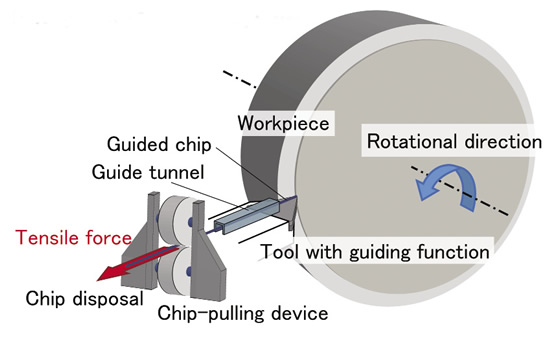
Researchers at Nagoya University in Japan developed a chip-pulling system to alleviate jamming that can occur when turning low-carbon steel and aluminum. Image courtesy Burak Sencer.
The focus then changed to designing a mechanical device that gently pulls the chip through the guide tunnel. “We had to measure the tension and determine a good pulling speed, as well as a good pulling force,” Sencer said. “If you pull too fast, the chip breaks and you’re back at square one.”
They mounted sensors under the pulling device to determine the forces the chip could handle.
“We can control the cutting feed, cutting speed and DOC in turning operations, but by controlling the chip tension, you’re adding an entirely new element,” Sencer said. “This can lead to a more efficient manufacturing operation.”
If chip tension can be regulated with the pulling device, for example, the cutting force reflected on the workpiece can be cancelled, according to Sencer. “In other words, it is like peeling a piece of fruit. As you cut the apple you pull the skin, which actually cancels the force that the cutting tool (knife) exerts on the workpiece. This allows precision turning of long, extremely slender parts. You push with the cutting tool and pull the chip to keep the part straight,” Sencer said.
The research, particularly the chip tension control, has received interest from both scientists and engineers, and the project led to the installation of a working vacuum system for chip removal in Murata’s turning machines.
Chip-pulling, however, is still a work in progress. Sencer is developing a more compact version that may utilize magnets to better control chip flow at different speeds and feeds. He is working on new proposals to improve the original chip-pulling concept.
For more information, contact Burak Sencer at [email protected] or visit www.mime.oregonstate.edu.
About the Author: Matt Jaster is senior editor of CTE. Contact him at (847) 714-0174 or [email protected].
Related Glossary Terms
- cutting force
cutting force
Engagement of a tool’s cutting edge with a workpiece generates a cutting force. Such a cutting force combines tangential, feed and radial forces, which can be measured by a dynamometer. Of the three cutting force components, tangential force is the greatest. Tangential force generates torque and accounts for more than 95 percent of the machining power. See dynamometer.
- cutting speed
cutting speed
Tangential velocity on the surface of the tool or workpiece at the cutting interface. The formula for cutting speed (sfm) is tool diameter 5 0.26 5 spindle speed (rpm). The formula for feed per tooth (fpt) is table feed (ipm)/number of flutes/spindle speed (rpm). The formula for spindle speed (rpm) is cutting speed (sfm) 5 3.82/tool diameter. The formula for table feed (ipm) is feed per tooth (ftp) 5 number of tool flutes 5 spindle speed (rpm).
- feed
feed
Rate of change of position of the tool as a whole, relative to the workpiece while cutting.
- rake
rake
Angle of inclination between the face of the cutting tool and the workpiece. If the face of the tool lies in a plane through the axis of the workpiece, the tool is said to have a neutral, or zero, rake. If the inclination of the tool face makes the cutting edge more acute than when the rake angle is zero, the rake is positive. If the inclination of the tool face makes the cutting edge less acute or more blunt than when the rake angle is zero, the rake is negative.
- shank
shank
Main body of a tool; the portion of a drill or similar end-held tool that fits into a collet, chuck or similar mounting device.
- turning
turning
Workpiece is held in a chuck, mounted on a face plate or secured between centers and rotated while a cutting tool, normally a single-point tool, is fed into it along its periphery or across its end or face. Takes the form of straight turning (cutting along the periphery of the workpiece); taper turning (creating a taper); step turning (turning different-size diameters on the same work); chamfering (beveling an edge or shoulder); facing (cutting on an end); turning threads (usually external but can be internal); roughing (high-volume metal removal); and finishing (final light cuts). Performed on lathes, turning centers, chucking machines, automatic screw machines and similar machines.


