Repeatability and accuracy are essential characteristics of any motion control system, and the objective of the design is to assure the desired trajectories can accurately follow through the working range of the system. In traditional XY gantry designs, the upper gantry member (Y-axis) is carried by two identical bottom axes (X1 and X2). Each X1 and X2 axes motor/screw/bearing systems are separated by finite distance orthogonal to the direction of the axes.
Because of the manufacturing precision of the components, such as linear guides deflections, ballscrew lead errors, axes misalignment and the variation of the position errors in X1 and X2 axes controllers, XY gantries orthogonality is affected. As Y-axis with load traverses across XY plane, it also introduces X axes position errors that are Y-axis position dependent.
The current approach to this design challenge is to implement 2-D position error mapping or suspend Y axis on the flexible members (flexures) and to independently control X1 and X2 axes to assure orthogonality. This approach reduces system bandwidth and provides small range of angle adjustment, usually within not more than 1 degree.
There are also many applications, where large Theta angle is an intentional feature of the system design (X-Y-Theta) to allow alignment of the work tool to the non-orthogonally located objects or to align patterns.
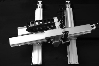
IntelLiDrives has designed and manufactured an innovative large area XY gantry where Theta angle can exceed 20 degrees. The new kinematic approach allows large relative motions of the independent X1 and X2 parallel axes. Such method allows to control orthogonality in XY plane or intentionally introduce large Theta rotation of the Y-axis about X1 and X2 axes, but also rotate Y-axis around virtual programmable point.
The system contains two pivot points on X1 and X2 axes to allow Y cross-axis to rotate around each of X-axis and be displaced linearly about each of them.
Though the current system manufactured with motorized ballscrew actuators with brushless servo motor/encoders, given approach also readily lends itself to system design with direct drive linear servo motors.
This gantry design covers more working area than robots using delta kinematics, which are also more expensive and bulky.
Optional Z-axis can be also easily installed.
The dual axes' gantry controller can independently control both X1 and X2 axes positions and theta (X1-X2).
The ability of independent X1 and X2 axes' control, allow them to be displaced any programmable distances, which in turn, allows Y-axis rotation around any programmable pivot point.
The system described in this article was designed for the XY travel 800 x 800 mm travel, with 20 degrees Y-axis rotation. Theta angle control achieved resolution 1 arc-sec with repeatability 3 arc-sec. Design can be extended to larger XY travels and Theta adjustment if required.


