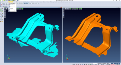
The latest release of VISI launches a new module for reverse engineering, along with new and enhanced functionality for both CAD and CAM processes, specifically designed for the mold and die market. As part of a wider project for reverse engineering, the new VISI 2018 R2 officially launches a dedicated module which provides a reverse engineering module within VISI’s existing modelling and machining environment. It allows a points cloud to be loaded, and the relative mesh created by setting different options for refining and smoothing.
VISI Product Manager Marco Cafasso says: “The Reverse Engineering module is completely integrated inside VISI, and means a point cloud can be loaded either from a Hexagon Romer Absolute Arm or an external file, and generate the desired, optimized mesh with special tools.
“This mesh can then be the starting point to create the relative surfaces through the modelling function, or used as it is for machining purposes.”
Overall, VISI 2018 R2 contains almost 250 items of new and enhanced functionality, including updates to the direct modelling capabilities, which provide additional editing for both solids and surfaces.
The new Edit Face means solid bodies can be edited simply by moving or pulling the selected faces, and concentric faces can be automatically selected and edited accordingly. “For example, the size of a pocket with holes – or the size of a solid body – can be changed with this new tool quickly and easily,” he says
Enhancements to both Surface Extension and Fill Holes means the designer can work directly on a solid body’s faces and not just on the surfaces, which Cafasso says provides considerable time savings on the solid model’s design and editing phase.
Another new CAM function is Toolpath Mirroring, which copies the current project, mirroring all its toolpath operations. This can be achieved on any 2-axis, 3-axis, 3+2-axis, and 4/5-axis toolpaths generated by VISI. “It retains the original cutting directions for all the operations, and is a major time saver for preparing toolpaths on mirrored geometry, which is widely used in the automotive market,” he adds.
The user experience for VISI has been enhanced in the latest version with the introduction of a more intuitive and dynamic workplane management, improved face selection on solids, and new contextual toolbars.
“The dynamic workplane management provides greater flexibility and ease of use as the workplane is dynamically and automatically orientated as soon as the desired face of a solid is selected during any operation. Updates to the faces selection allows matching faces to be selected – in fact, it’s now possible to select matching faces by providing specific conditions such as planar, cylindrical and fillet face types, along with radius condition, orientation and colours, to dynamically select similar faces,” Cafasso says.
Finally, a contextual toolbar on active selection allows users to switch between the contextual functionalities, which Cafasso says provides a simpler and more intuitive user experience.
Related Glossary Terms
- computer-aided design ( CAD)
computer-aided design ( CAD)
Product-design functions performed with the help of computers and special software.
- computer-aided manufacturing ( CAM)
computer-aided manufacturing ( CAM)
Use of computers to control machining and manufacturing processes.
- fillet
fillet
Rounded corner or arc that blends together two intersecting curves or lines. In three dimensions, a fillet surface is a transition surface that blends together two surfaces.
- toolpath( cutter path)
toolpath( cutter path)
2-D or 3-D path generated by program code or a CAM system and followed by tool when machining a part.


