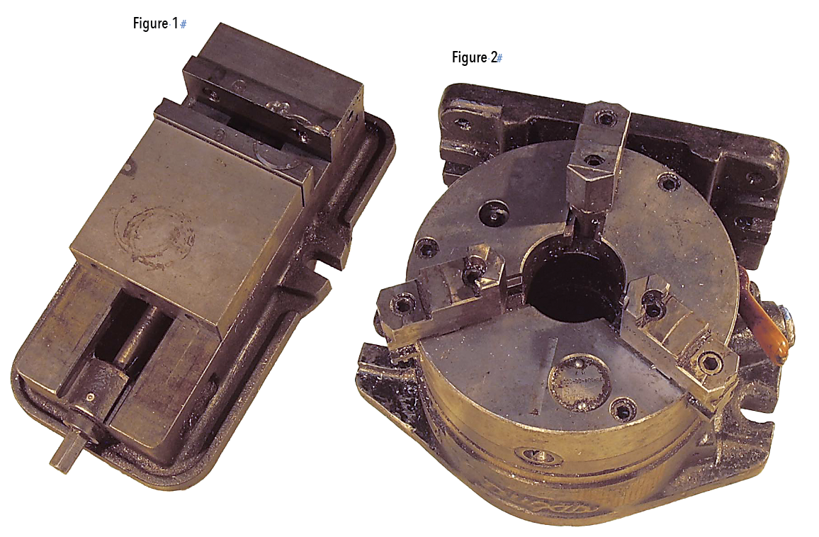
When holding parts for milling operations, the geometry of the part determines how best to clamp it. For parts with flat surfaces a vise is often the best solution. Figure 1 shows a typical milling vise. For round parts a scroll mounted on an index might be best. Figure 2 shows such a tool.
The vise in Figure 1 has a wedge arrangement in the sliding jaw. That feature improves accuracy and is important. The screw that tightens the vise pushes against a wedge that slides in the vise bed. That wedge pushes against another wedge with opposite geometry that is attached to the sliding jaw.
The result is that the clamping force between the movable and stationary jaws is matched by an equal force that pushes the movable jaw against the vise bed. This prevents the movable jaw from tilting and rising relative to the fixed jaw, and thus holds the clamped part square in the vise jaws. Vises without this feature introduce error in the clamping operation, and make for less accurate machining.
These wedge clamp vises have been around for a lot of years, and there are many manufacturers. Some take care with accuracy, grinding all the mating faces. Some, not so much. Years ago, a tool salesman told me, “An inaccurate tool is an expensive tool; an accurate tool is a good tool.” So true.
If you have a setup with multiple vises, it is really nice to have vises with identical dimensions.
Figure 2 shows an index I have had for 40 years. I use it for clamping round parts because it is accurate and durable. Round parts can be clamped with a milling vise with machined soft jaws or vise jaw accessories, but I use the scroll chuck index, if possible, especially if machining multiple parts. The clamping surface of a round part may have a diameter tolerance that could put the part off center if clamped with a vise. With a scroll chuck the clamping action centers the part on the chuck for better results. Finally, both vise jaws and chuck jaws can be made from soft material and can be machined for a workpiece with a special geometry. Soft jaws for milling vises and scroll chucks are available from tool distributors. Some milling vises on the market have the jaw bolt hole location at variance from other manufacturers, so beware of that when buying a vise.
Some of the specialty vise jaws have unique features that can be handy. I have a vise jaw set that has hydraulics in one jaw so six parts can be clamped simultaneously. You don’t want to be precluded from a clamping option because the vise you have has an unusual bolt pattern. The index I use has American Standard 8" chuck tongue and groove jaws, which are interchangeable with the jaws on an 8" chuck I have on a lathe. That simplifies things when machining soft jaws. I can machine soft jaws on the mill or lathe for use on the other machine. More about that in my next article. Details are important.
Related Glossary Terms
- centers
centers
Cone-shaped pins that support a workpiece by one or two ends during machining. The centers fit into holes drilled in the workpiece ends. Centers that turn with the workpiece are called “live” centers; those that do not are called “dead” centers.
- chuck
chuck
Workholding device that affixes to a mill, lathe or drill-press spindle. It holds a tool or workpiece by one end, allowing it to be rotated. May also be fitted to the machine table to hold a workpiece. Two or more adjustable jaws actually hold the tool or part. May be actuated manually, pneumatically, hydraulically or electrically. See collet.
- flat ( screw flat)
flat ( screw flat)
Flat surface machined into the shank of a cutting tool for enhanced holding of the tool.
- gang cutting ( milling)
gang cutting ( milling)
Machining with several cutters mounted on a single arbor, generally for simultaneous cutting.
- grinding
grinding
Machining operation in which material is removed from the workpiece by a powered abrasive wheel, stone, belt, paste, sheet, compound, slurry, etc. Takes various forms: surface grinding (creates flat and/or squared surfaces); cylindrical grinding (for external cylindrical and tapered shapes, fillets, undercuts, etc.); centerless grinding; chamfering; thread and form grinding; tool and cutter grinding; offhand grinding; lapping and polishing (grinding with extremely fine grits to create ultrasmooth surfaces); honing; and disc grinding.
- lathe
lathe
Turning machine capable of sawing, milling, grinding, gear-cutting, drilling, reaming, boring, threading, facing, chamfering, grooving, knurling, spinning, parting, necking, taper-cutting, and cam- and eccentric-cutting, as well as step- and straight-turning. Comes in a variety of forms, ranging from manual to semiautomatic to fully automatic, with major types being engine lathes, turning and contouring lathes, turret lathes and numerical-control lathes. The engine lathe consists of a headstock and spindle, tailstock, bed, carriage (complete with apron) and cross slides. Features include gear- (speed) and feed-selector levers, toolpost, compound rest, lead screw and reversing lead screw, threading dial and rapid-traverse lever. Special lathe types include through-the-spindle, camshaft and crankshaft, brake drum and rotor, spinning and gun-barrel machines. Toolroom and bench lathes are used for precision work; the former for tool-and-die work and similar tasks, the latter for small workpieces (instruments, watches), normally without a power feed. Models are typically designated according to their “swing,” or the largest-diameter workpiece that can be rotated; bed length, or the distance between centers; and horsepower generated. See turning machine.
- milling
milling
Machining operation in which metal or other material is removed by applying power to a rotating cutter. In vertical milling, the cutting tool is mounted vertically on the spindle. In horizontal milling, the cutting tool is mounted horizontally, either directly on the spindle or on an arbor. Horizontal milling is further broken down into conventional milling, where the cutter rotates opposite the direction of feed, or “up” into the workpiece; and climb milling, where the cutter rotates in the direction of feed, or “down” into the workpiece. Milling operations include plane or surface milling, endmilling, facemilling, angle milling, form milling and profiling.
- milling machine ( mill)
milling machine ( mill)
Runs endmills and arbor-mounted milling cutters. Features include a head with a spindle that drives the cutters; a column, knee and table that provide motion in the three Cartesian axes; and a base that supports the components and houses the cutting-fluid pump and reservoir. The work is mounted on the table and fed into the rotating cutter or endmill to accomplish the milling steps; vertical milling machines also feed endmills into the work by means of a spindle-mounted quill. Models range from small manual machines to big bed-type and duplex mills. All take one of three basic forms: vertical, horizontal or convertible horizontal/vertical. Vertical machines may be knee-type (the table is mounted on a knee that can be elevated) or bed-type (the table is securely supported and only moves horizontally). In general, horizontal machines are bigger and more powerful, while vertical machines are lighter but more versatile and easier to set up and operate.
- tolerance
tolerance
Minimum and maximum amount a workpiece dimension is allowed to vary from a set standard and still be acceptable.
Author

Brandt Taylor is owner of Berlin, Massachusetts-based Taylor Engineering, a machine shop.