Mastercam 2017 for SOLIDWORKS
Mastercam 2017 for SOLIDWORKS
Mastercam 2017 for SOLIDWORKS is a CAM application that is fully integrated into SOLIDWORKS. Users can program parts directly in SOLIDWORKS using Mastercam's industry-leading toolpaths and machining strategies. In addition to all the improvements to Mastercam Mill and Lathe, Mastercam 2017 for SOLIDWORKS features the Analyze Toolpath and improved Tplanes.
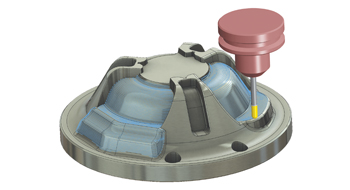
Mastercam 2017 for SOLIDWORKS is a CAM application that is fully integrated into SOLIDWORKS. Users can program parts directly in SOLIDWORKS using Mastercam's industry-leading toolpaths and machining strategies. In addition to all the improvements to Mastercam Mill and Lathe, Mastercam 2017 for SOLIDWORKS features the Analyze Toolpath and improved Tplanes.
To make your job easier, Analyze Toolpath is used to display toolpath information such as coordinates, direction, and operation number when you hover over any part of the tool motion. Green and red arrows display at the start and end points of the entire path. When hovering over an element that is not an endpoint, a tooltip will display information that is specific to the entity.
To simplify your work, Tplanes are now associated to the SOLIDWORKS geometry that was used to create them. When a modification to the SOLIDWORKS geometry affects multiple planes, Mastercam for SOLIDWORKS displays a message asking you to confirm your changes.
CAD Functions
The Mastercam 2017 tab now includes a CAD Functions menu which contains the Create Boundary and Create Letters functions. These will create SOLIDWORKS geometry. The Roll-Unroll function is used to wrap geometry about an axis or to unwrap rolled entities to make them lie flat. Mastercam creates a sketch from the resulting geometry.
Also available in the Mastercam 2017 for SOLIDWORKS release is:
- To view real-time operation data about selected toolpaths, you can choose the Display toolpath statistics option.
- Category-specific icons are now included on the SOLIDWORKS ribbon bar. All drop-downs now have an icon that matches the first of the functions to make it easier to find what you are looking for.
- Those who purchase or update to Mastercam Mill 2017 or Mastercam Lathe 2017 will also be able to use the corresponding version of Mastercam for SOLIDWORKS.
- New Chip Break is available in Mastercam for SOLIDWORKS Lathe and is valuable when working with stringy materials, and allows you to set length and time conditions, retract, and dwell options.
- Code Expert enhancements including fonts and colors in NC Configuration and character coding.
- Mastercam Simulator Auto Start which allows Mastercam Simulator to immediately begin to play once a sufficient amount of data has been transferred.
- Custom Tool Display allows users to define a tool using parametric properties along with a custom profile that can be imported from a CAD file.


