Aluminum can be hard to drill, despite its easy rep
Aluminum can be hard to drill, despite its easy rep
When drilling, perhaps no variable is as important as the workpiece material. It dictates drill geometry and substrate, tool coating, coolant application, and speeds and feeds. While known for its relative softness and ductility, misconceptions abound among those who regularly drill aluminum.
When drilling, perhaps no variable is as important as the workpiece material. It dictates drill geometry and substrate, tool coating, coolant application, and speeds and feeds.
While known for its relative softness and ductility, misconceptions abound among those who regularly drill aluminum.
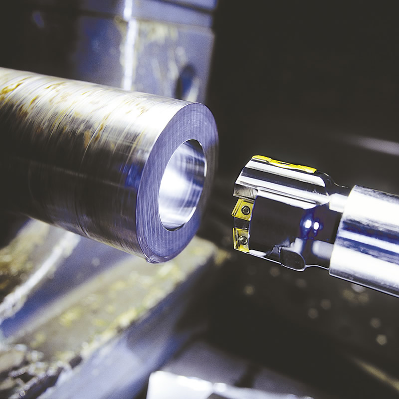 "Aluminum is considered by many to be one of the easiest machining materials, but it does present its own unique challenges"—particularly when drilling, explained Elliott Frazier, a product manager at Tungaloy America Inc., Arlington Heights, Ill. "Aluminum is a generally soft, nonferrous, ductile material with low density and naturally high resistance to corrosion. Aluminum is difficult to drill because its ductility and softness causes the material to make constant prolonged contact with the rake face, or cutting edges, of a drill."
While there are many different aluminum alloys with unique machinability characteristics, Frazier said the most widely drilled aluminum alloys are 6061 and 7075, adding that there are pockets of aerospace and medical work that use specialty alloys exclusively.
Edges, Flutes and Coatings
The two main issues when drilling aluminum, explained Chad Lynch, field sales engineer for Allied Machine & Engineering Corp. (AMEC), Dover, Ohio, are chip formation and chip evacuation. "If you approach it without the proper tool geometry, without the proper coating, without the proper coolant, it can very quickly turn into a situation where long, stringy chips are wrapping themselves around the tool."
Frazier added built-up edge to the list of primary challenges when drilling aluminum alloys. The aluminum will build up and adhere to the cutting edge and interfere with the formation of new chips from the parent material, which can lead to chip packing, as flutes become clogged. This leads to deposits of aluminum adhering to the drill, promoting even further adhesion and chip packing.

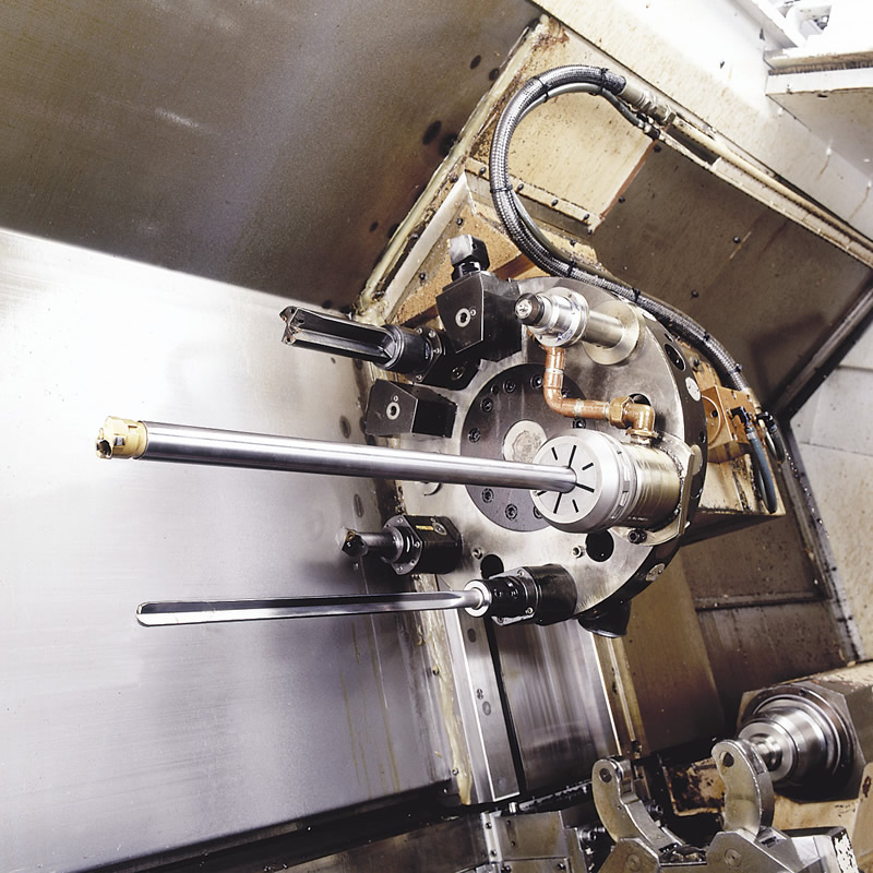
The guide path pressure of a gundrill can impact surface finish, depending on coolant lubricity, due to the inherent plasticity of aluminum. Image courtesy Sandvik Coromant.

"Chips tend to 'string out' because of the softness of the material," Lynch explained. "The primary way to get around that is through geometry." AMEC offers an aluminum-specific geometry for its TA product line, which has a high rake angle that effectively forms a chip in gummier, 6061-type materials, he said. A higher rake creates more shear in the cut and forces the material into the impact site on the tool.
The main difference between drilling aluminum and harder materials, noted Jason Hout, global DHM (deep hole machining) product and application specialist for Sandvik Coromant Co., Fair Lawn, N.J., is that the shear point of aluminum is low enough that it can be sliced by the tool's cutting edge, as opposed to being pushed out
of the way when machining harder materials. This means an upright, high shear angle with a minimal edge hone is ideal for drilling aluminum.
"Generally, drills with a high helix angle, polished flutes and 130° to 140° point angle will provide the best chip evacuation and cutting performance," Frazier said. "However, since aluminum is so soft, drilling operations using the aforementioned geometry tend to present difficulties in maintaining proper hole diameter and sidewall surface finish. If maintaining hole size, finish and hole roundness are the goals, using a straight-flute, through-coolant drill is advantageous."
However, a sharp edge is a weak edge, and many aluminum grades contain high levels of silica—a hard, glass-like particulate in the matrix of the aluminum that can rapidly break down a tool's edge. "Wear [from silica] can sometimes be combatted with coatings or by switching from carbide to a superabrasive tool material like PCD," Hout said.
When applying a carbide tool, it's important that it doesn't have an aluminum-based coating, because the aluminum will tend to stick to the workpiece surface, he added. Common coatings such as Al2O3 or AlTiN, when brought into contact with aluminum under heat and pressure, will not only react with the part, but have abrasive properties that can contribute to BUE. Instead, Hout recommends either titanium diboride or an amorphous diamond film.
If those aren't available, uncoated carbide with a polished surface provides more-than-adequate performance in most applications, Hout noted. "You want the flutes polished to help material slide out, and if there is a radius within the flute, you don't want a square edge or a straight wall unless it's unavoidable [such as when gundrilling]."
Frazier recommends a micrograin carbide with a hardness from 92 to 93 HRA for low-silicon alloys, but said some aluminum alloys used for forgings or castings contain more than 11 percent silicon and are best approached with drills tipped with PCD or diamond-like carbon.
"Usually, coatings are not applied to drills in aluminum applications, as a majority of coatings contain aluminum," he said. Because the majority of coatings contain aluminum as one of their base constituent elements, Frazier said some manufacturers have begun utilizing a titanium-zirconium-nitride coating in aluminum applications. "But the conventional wisdom in this field is to utilize a sharp, high-polished, uncoated carbide drill."


Using a straight-flute, through-coolant drill is advantageous if maintaining hole size, finish and hole roundness is the goal. Image courtesy Tungaloy.

One such manufacturer is R.I. Carbide, a tool grinder and machine shop in Smithfield, R.I., that offers its ZETA ZrN coating as an alternative to TiN when extra lubricity is needed.
"We had a customer who needed to drill 3,000 holes in a plate of aluminum, and if they broke a drill machining one hole, the whole part was scrap," said John Lombardi, company president. "So they came to us with the problem, and we made a 0.156"-dia. drill with a ½" base about 3" long for the job." R.I. Carbide used the ZETA coating on the drill, and by running that highly lubricious drill with through-coolant capability at high speeds, the customer was able to successfully complete the part on the first pass.
Cool Down
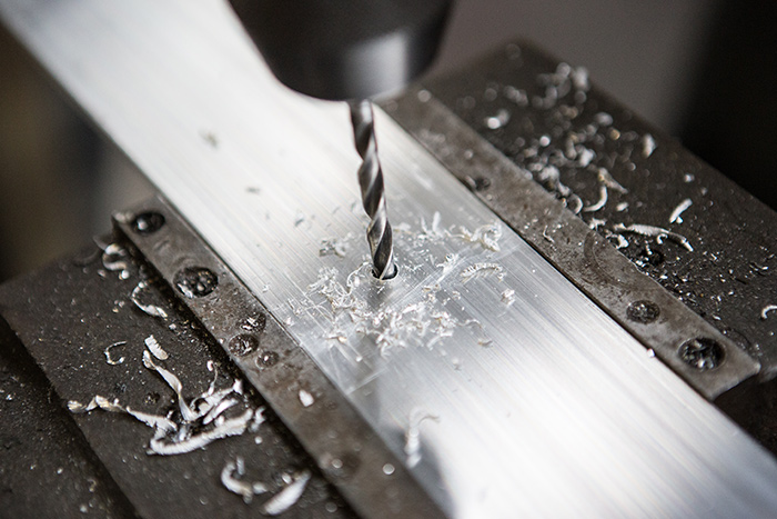
Proper chip evacuation involves proper application of coolant, and drilling aluminum is no exception. Pecking is always an option, but many part manufacturers like to avoid withdrawing the drill when possible, which means polished flutes and through-coolant drills are the order of the day.
"Especially when you go to longer depths, the issue is always coolant flow for chip evacuation, and that's not anything unique to aluminum," noted AMEC's Lynch. "We prefer not to peck, and I feel that if people have to do any pecking, it's probably because they're not forming a good chip. We've actually found that the type of cutting fluid is less important than the concentration—the higher the concentration, the better your results, generally speaking."
Tungaloy's Frazier always recommends through-coolant. "Higher metal-removal rates require [applying] a lot of coolant, very quickly, to move the chips from the cutting zone, and mrr is typically very high in aluminum." Flood coolant would require peck cycles, and minimum-quantity lubrication simply doesn't have the displacement value when holemaking, especially drilling deep holes, he said. "The higher the flow, and higher the pressure, the better."
Sandvik Coromant's Hout has observed at least one characteristic unique to aluminum when deep-hole drilling. "When using self-guided drills like gundrills, because of the plasticity of aluminum, the guide path pressure can impact the finish of the hole either positively or negatively, depending on the lubricity of the coolant," he said. Neat cutting oil typically results in a smooth finish, while a synthetic, water-based fluid might allow some of the aluminum to stick to the guide path, creating a rough, "smeared" finish.
Running at high cutting speeds while resisting the temptation to overfeed and applying a coolant with high lubricity and moderate-to-low viscosity is the best way to ensure a fine surface finish, Hout said. "You want the oil to move fast."
Fast Times
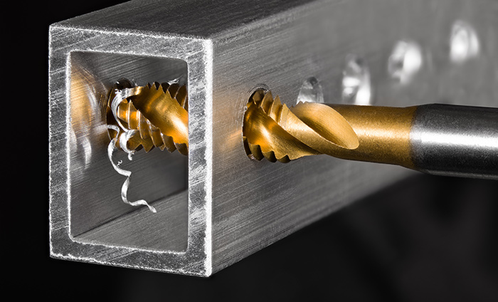
How high can those cutting speeds be? According to Hout, modern machinery has not yet advanced to the point where the surface speed ceiling for aluminum can be hit.
"The threshold for aluminum is something like 60,000 sfm, which is enormously fast," he said. "I've seen aluminum run at 24,000 sfm with an uncoated carbide insert, and it didn't harm the aluminum or the insert. I tell our customers that, within a safe working environment, don't be afraid to crank it up because I've seen that higher speeds in aluminum gets you both better tool life and a better surface finish."
Because aluminum is considered by many to be cheap and easy to work with, it's easy to fall into the trap of thinking any machining setup will work. However, some of the "easiest" materials to machine end up yielding the lowest profit margins at the end of the job, according to Tungaloy's Frazier.
"If more shops are able to do the work on 'easy' materials, there is more competition for those same jobs, inevitably driving down the price of cutting aluminum," he said. "In this sense, it is important to maximize your speed and efficiency when working with these materials, using updated tooling and advanced concepts, in order to stay competitive."

American/English
While North Americans know it as "aluminum," most English-speaking countries use the suffix "-ium." The Canadian Oxford Dictionary lists the spelling as "aluminum," while the Australian Macquarie Dictionary prefers "aluminium." The reason?
"In 1926, the American Chemical Society officially decided to use aluminum in its publications; American dictionaries typically label the spelling aluminium as 'chiefly British,'" explained Tungaloy America Inc.'s Elliott Frazier. "The earliest citation given in the Oxford English Dictionary for any word used as a name for this element is alumium, which British chemist and inventor Humphry Davy employed in 1808 for the metal he was trying to isolate electrolytically from the mineral alumina.
"Essentially, the British thought 'aluminium' sounded more classical and scientific, so they added the extra letter."
—E. Jones Thorne

Flowdrill, Baby, Flowdrill
Drilling involves generating chips. It's just a given—after all, the material that's removed has to go somewhere, right? But while a process that doesn't generate chips might not sound like drilling to some, St. Louis-based thermal-friction-drilling specialist Flowdrill Inc. offers an alternative to traditional drilling.
"Thermal-friction drilling is a process that involves generating heat through friction and pressure," said Mitch Ray, president of Flowdrill. "We create what we refer to as a bushing in thin-walled material, which extends approximately three to four times the original wall thickness."
This bushing adds more thread to the hole and gives the customer an alternative to current fastener methods like weld nuts or threaded inserts. Once the bushing is created, a form tap can create threads, or a self-threading screw can be inserted to complete the job. There are no chips created in either case.

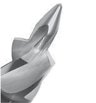
Flowdrill's Aludrill geometry is specially designed for use in aluminum. Image courtesy Flowdrill.

Every tool bit diameter has a certain set of parameters, Ray explained. For example, a ¼-20 thread size would require a tool to be run at 2,400 rpm in aluminum or mild steel, require 1.5 hp and have a cycle time of about 3 seconds per hole. The bit contacts the material, and the friction of that contact heats the material while the pressure behind the bit pushes through the material and forms the bushing. There is no external heat source, and Flowdrill bits can be used on any standard CNC machine without any special adapters.
The company's newest geometry is called the Aludrill, which is designed specifically for aluminum.

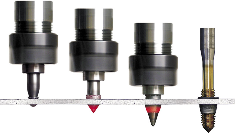
Thermal-friction drilling creates a hole and a bushing—but no chips—through the use of heat and pressure. Image courtesy Flowdrill.

"Unlike our other bits, it doesn't require our special lubricant; it can operate with standard machine coolant," Ray said. "It also countersinks a chamfer into the material, which makes it the only one of our bits that generates a chip."
On a standard Flowdrill bit, a polygon is ground, consisting of four peaks and four valleys, each referred to as "lobes," which are what generate the friction and cause the heat. The Aludrill eschews this geometry in favor of more contact with the metal, which creates enough friction in the softer aluminum to generate sufficient heat.
"We've got some large applications for the Aludrill," Ray said. "Last year, it was used on the new Ford F150 pickup, making holes in the front aprons of those trucks. They use a self-tapping screw to attach the different wiring lines to the front of the trucks."
—E. Jones Thorne

Contributors
Allied Machine & Engineering Corp.
(330) 343-4283
www.alliedmachine.com
Flowdrill Inc.
(314) 968-1134
www.flowdrill.com
R.I. Carbide
(401) 231-1020
www.ricarbide.com
Sandvik Coromant Co.
(800) SANDVIK
www.sandvik.coromant.com/us
Tungaloy America Inc.
(888) 554-8394
www.tungaloyamerica.com


