Bushings Get It Straight
Bushings Get It Straight
Guide bushings are used in difficult holemaking applications to ensure that the drill produces round straight holes. This article discusses the types of bushings commonly used and the materials they are made from. Guidelines for sizing bushings for a given operation are also supplied.
When you think about raising machine uptime, improving hole quality, and lowering tooling costs, you might not give much thought to the bushings you're using. But perhaps you should.
Holemaking and hole-finishing operations such as gundrilling, reaming, tapping, multispindle drilling, and drilling to depths greater than 2 diameters require the use of guide bushings. Bushings come in a wide range of lengths, IDs, ODs, designs, and materials. Selecting the proper bushing style for a given application can ensure the production of round, straight holes, no matter how challenging the application may be.
 Figure 1: Standard bushings may be headed or headless and may include oil grooves (at right). | |
Bushing designs include headless or headed press fit (Figure 1), fixed renewable, and slip fixed renewable.
Headless press fit. This low-cost bushing, designed for single-stage drilling, is pressed into the jig plate until flush with its surface. Because it is headless, the bushing is ideal for use in limited space and close hole arrangements. When worn, the bushing must be drilled out.
Headed press fit. This inexpensive bushing is used when high pressure, caused by high removal rates that produce chip buildup between the spindle and the bushing, could force a headless bushing through the jig plate.
Fixed renewable. This type is used with bushing liners and is held in place with a lock screw. It is designed for use on part runs longer than the life of a typical bushing, because it is easy to replace when worn without removing the jig from production. Bushing wear can be caused by tool impact, a particularly hard workpiece material (because chips of the material contact the bushing wall as they exit the drill flutes), a nonperpendicular angle of entry, or poor alignment.
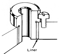 Figure 2: Bushing liners help ensure a precise location point for the replacement of slip or fixed renewable bushings and protect the jig plate from wear caused by bushing replacement. A headless liner is depicted here. | |
Bushing liners facilitate bushing replacement. The liners, available in headed or headless styles, are pressed permanently into the jig (Figure 2). They maintain a precise locating point for bushing insertion and protect the jig plate from wear caused by frequent bushing replacement. Headed liners are recommended for applications in which high pressure or pounding could push liners through the jig plate.
Slip fixed renewable. Used with a headed or headless bushing liner permanently pressed into the jig, a slip fixed renewable bushing is locked in place with a lock screw or a slip lock. This permits more than one operation to be performed on the same hole, such as drilling and reaming, without disturbing the workpiece. Drill and reamer bushings can be interchanged in the same liner without affecting centering accuracy. Slip bushings feature a knurled head to aid removal.
The various bushing designs are identified by a combination of letters and symbols in accordance with American National Standards Institute (ANSI) designations. The ANSI identification system is illustrated in Figure 3.
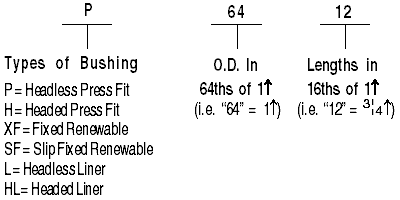 Figure 3: The ANSI identification system for bushings. |
 Figure 4: Bushings may include coolant bores or slots to provide chip-flushing capability. | |
Some applications require special bushing designs, such as bushings with longer lengths, which can butt up to the workpiece and afford greater accuracy; bushings with thin walls for use in high-precision close hole patterns; and directed-coolant bushings for drilling hardened steels that require cooler-running drills. Bushings also may come with coolant holes through the bushing wall to permit effective chip flushing during cutting (Figure 4). This feature is especially useful in high-production applications involving high feed rates or when the bushing is in direct contact with the workpiece.
No matter what style of bushing is chosen, it should have the following characteristics: a superfinish to minimize wear, a blended radius at the top of the bushing to minimize tool damage resulting from misalignment, a high Rockwell hardness to maximize bushing life, concentricity and roundness to maintain positioning accuracy, an OD chamfer at the bushing bottom to prevent peening over (mushrooming ends caused by chip accumulation), and an ID break or chamfer to facilitate chip clearance and reduce tool wear.
Fit and Installation
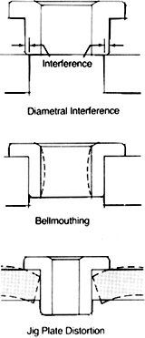 Figure 5: Improper fits between the bushing and the jig plate can cause bellmouthing or jig-plate distortion. Interference fits are recommended. | |
Accuracy in production operations depends on proper mounting-hole preparation and bushing and liner installation. Diametral interference fits and the distance between the bottom of the bushing and the workpiece are important factors to consider.
Diametral interference fits of 0.0005" to 0.0008" for headless press fit bushings and 0.0003" to 0.0005" for headed press fit bushings are recommended between the bushing OD and the mounting hole ID to provide adequate gripping force. This fit typically will hold the bushing in the jig without distorting the jig plate or the bushing bore. As Figure 5 illustrates, improper fits can cause bellmouthing or jig-plate distortion. Fixed renewable bushings require a diametral clearance of 0.0001" to 0.0006" to ensure accuracy and ease of replacement.
In terms of OD, bushings should be twice the diameter of a typical twist drill. A bushing should be long enough to hold the drill's entire shank steady. If the bushing is too short, the tool will be allowed to bend. However, if the bushing is too long, the drill will have to be longer than necessary to produce the desired hole. The results of this latter scenario may include accelerated drill wear, chip interference, drill breakage, and poor hole roundness and straightness.
Clearance between the bottom of the bushing and the top of the workpiece should be 1 to 1.55 the drill diameter to allow room for chip removal and thus minimize chip abrasion of the bushing (Figure 6). Bushings can be provided with chipbreaker ends to facilitate chip removal (Figure 7).
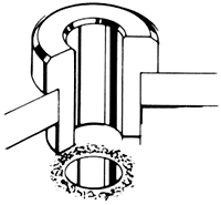 Figure 6: Locate the bushing a sufficient distance from the jig plate to permit chip clearance. | |
Figure 7: Bushings may incorporate chipbreaker bottom edges. | |
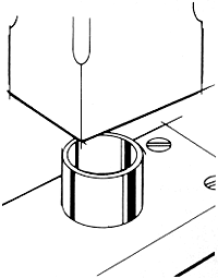 Figure 8: Maintain centerline perpendicularity when pressing bushings into the jig plate. | |
In some cases, it's best to leave a distance equal to half the bushing ID between the bushing and the workpiece to permit chip clearance. The distance should be greater for materials such as soft steels that produce long stringy chips.
If the tool must approach the workpiece at a nonperpendicular angle, the bottom of the bushing should be parallel to the workpiece surface after being cut or ground to the angle necessary to match the workpiece contour and should be located very close to the workpiece surface.
The bushing bore should allow 0.0001" to 0.0007" of clearance for the cutting tool, depending on the tool's diameter. This allows the tool to approach the workpiece without interference while providing enough support to help the tool produce round, straight holes. Drill bushings and reamer bushings each have specific hole tolerances related to bushing ID and OD. Bushing-bore concentricity should range from 0.0000" to 0.0003" TIR on finish-ground parts up to 0.5000" in diameter; for parts larger than that, concentricity should range between 0.0000" and 0.0005" TIR.
Jig plates, or multiple bushing-bore fixtures in the case of high-production operations, are usually made of cast iron or unhardened steel. They should be thick enough to hold and support the bushings. When using a thick bushing plate to support a long drill, go with an extended-length bushing that's relieved to maintain proper contact length through the plate. Bushing mounting holes should be jig-bored or sized with a reamer to ensure roundness.
Use a hand arbor to install press-fit bushings in jig plates to ensure centerline perpendicularity to the plate (Figure 8).
Bushing Wear
After guiding cutting edges for many cycles, bushings begin to wear. Along with proper installation, selecting the optimum bushing material for a given application can delay this wear considerably.
Drill bushings are made from either high-carbon chromium steel (with a bore hardness of Rc 58) for low-production applications in which low price supersedes wear resistance, nitrided alloy steel for applications involving deep holes or abrasive work materials, or carbide for maximum wear resistance. Nitrided steel bushings generally provide up to 2.55 the wear resistance of standard steel, while carbide bushings provide up to 2505 the wear resistance of steel, depending upon the application. Carbide bushings are becoming increasingly popular among shops engaged in high-production operations. Though more expensive initially, carbide is less vulnerable to chip abrasion than other materials and reduces the number of bushing replacements needed, saving both replacement time and the cost of replacement bushings. For smaller part runs, justifying the cost of carbide bushings may be impossible. In these cases, nitrided alloy-steel bushings are more economical and still provide significant wear resistance.
Most importantly, nitrided-steel and carbide bushings maintain their integrity longer, producing higher quality holes. Machinists often overlook the key role bushings play in the production of round, straight holes. If you select and properly apply the appropriate bushing style, specifications, and material, drill bushings can help improve metalcutting accuracy and repeatability while reducing tool change downtime.
About the Author
George Taylor is director of application engineering with Briney Tooling Systems, Bad Axe, MI.